
Device for vacuuming away drilled material when drilling with a drill in masonry and similar

A drill bit and drilling technology, which is applied in the direction of drilling/drilling equipment, parts of boring machine/drilling machine, maintenance and safety accessories, etc., and can solve the problem of small collection capacity of the collection chamber

Inactive Publication Date: 2009-12-23
ELECTROSTAR
View PDF7 Cites 6 Cited by
  • Summary
  • Abstract
  • Description
  • Claims
  • Application Information

AI Technical Summary

Problems solved by technology

In addition, the collection capacity of the collection chamber is also very small

Method used


Image

  • Device for vacuuming away drilled material when drilling with a drill in masonry and similar

Examples


Embodiment Construction

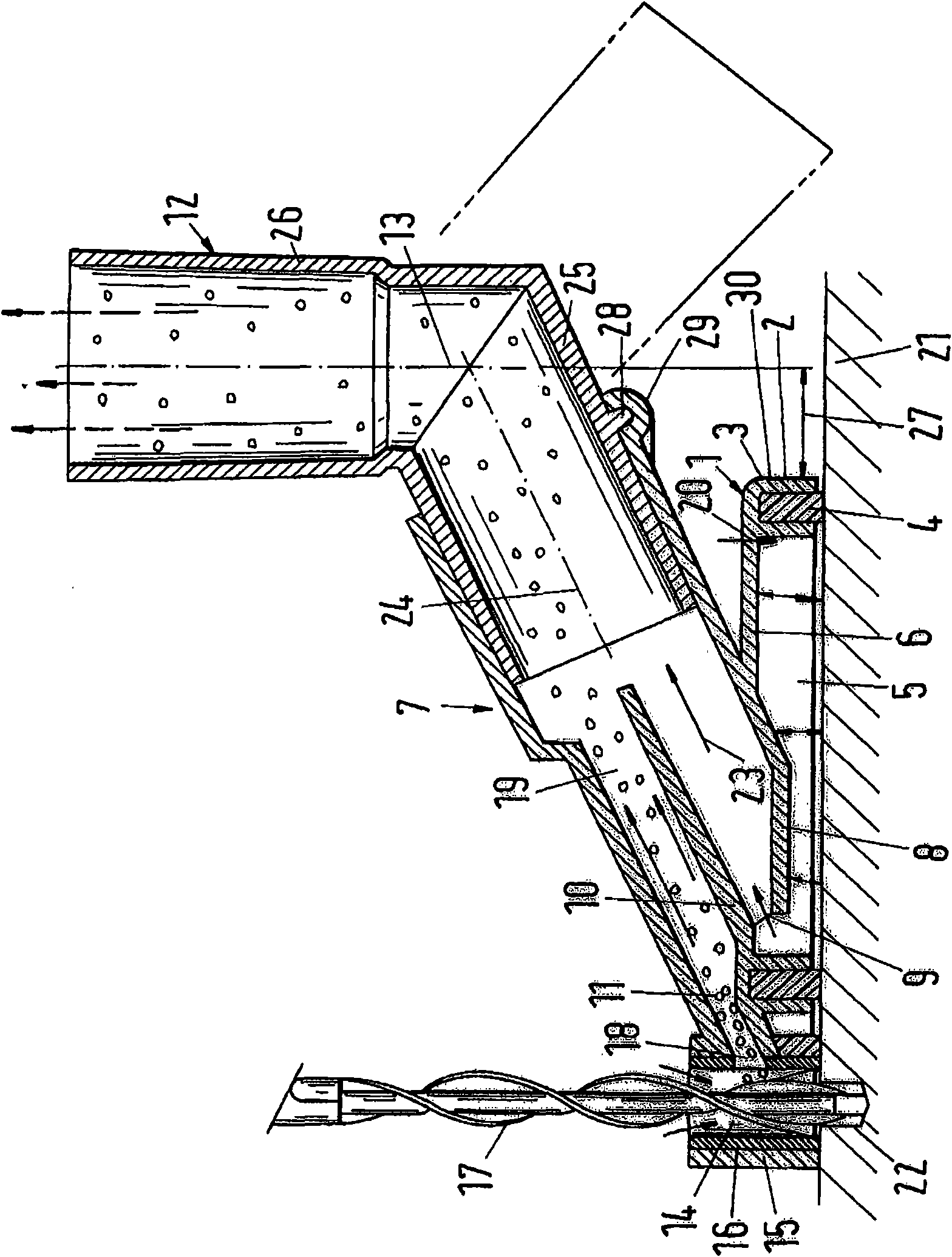
[0021] The suction device is used for suctioning the cuttings which are generated directly at the drilling site during drilling. The device has a base body 1 which can have any desired contour. On a part of the circumference it has a corner 2 bent at right angles, in which a recess 3 for accommodating a seal 4 is arranged. The seal protrudes beyond the edge 2 and surrounds a low-pressure chamber 5 , which is bounded on the peripheral side by the edge 2 with the seal 4 and delimited by the cover 6 of the base body 1 . Projecting into the low-pressure chamber 5 is a tubular connecting sleeve 7 which is advantageously made in one piece with the base body 1 . The connecting sleeve 7 protrudes beyond the base body 1 over most of its length. It projects slightly into the low-pressure chamber 5 with an end region 8 . The end region 8 has an opening 9 through which the low-pressure chamber 5 communicates internally with the connecting sleeve 7 .

[0022] Distributed in the connect...


PUM


Abstract

The present invention relates to a device for vaccuming away drilled material when drilling with a drill in masonry and similar, including a low pressure chamber, at least a suction point and a connector for a suction unit that sucks a cutting accumulated on the suction point. The invention is characterized in that the suction point (14) and the low pressure chamber (5) are separated in space. By means of the invention, it is capable of sucking the drilled material generated during a drilling period reliably without a damage of the walling surface and a relation of the device position.

Description

technical field [0001] The invention relates to a device for suctioning cuttings when drilling wall masonry etc. with a drill bit, having at least one low-pressure chamber, at least one suction point and a connection for a suction unit, The unit sucks away drill cuttings incidentally generated at the suction point. Background technique [0002] This device is used to suck up the cuttings incidentally produced when drilling wall masonry at the suction point so that they do not fall to the ground. For this purpose, the device is connected to the suction hose of a vacuum cleaner with which the cuttings are sucked from the suction point. At this time, a negative pressure is formed in the low-pressure cavity, which is responsible for making the device press against the wall masonry and be sucked tightly. It is therefore not necessary to hold the device by hand during drilling. The drill bit is loaded through an orifice in the wall of the low-pressure chamber. The drill cuttin...

Claims


Application Information

Patent Timeline
Patent Type & Authority Applications(China)
IPC IPC(8): B28D7/02B28D1/14
CPCB23B2270/30B23Q11/0046B23B47/00Y10T408/554Y10T408/50
Inventor E·布伦特内尔
Owner ELECTROSTAR
Learn More