
Dust removing device

A technology of dust removal device and dust removal chamber, which is applied to the separation of dispersed particles, chemical instruments and methods, and the use of liquid separators, etc., can solve the problems of small dust removal area, polluted environment, dust discharge, etc., so as to reduce labor intensity and reduce dust concentration. , the effect of improving the working environment

Inactive Publication Date: 2009-12-23
孙付江
View PDF0 Cites 1 Cited by
  • Summary
  • Abstract
  • Description
  • Claims
  • Application Information

AI Technical Summary

Problems solved by technology

Especially in places with heavy pollution, such as power generation enterprises, iron and steel enterprises and petrochemical enterprises, a large amount of dust will be generated when unloading materials into coal, mine and other silos, which not only seriously pollutes the environment, but also Great harm to the health of workers
In the prior art, the atomizing vacuum pulse dedusting device is a typical dedusting device. Its disadvantages are: there is only one dedusting and atomizing water nozzle on the upper part of the dedusting atomization chamber, and the dedusting area is small, and the dust and water mist The combination effect is poor, the dust removal rate is only 85% after treatment, and some dust is still discharged with the air, which cannot fully meet people's requirements

Method used


Image

  • Dust removing device
  • Dust removing device
  • Dust removing device

Examples


Embodiment Construction

[0020] The present invention will be further explained below in conjunction with the accompanying drawings.

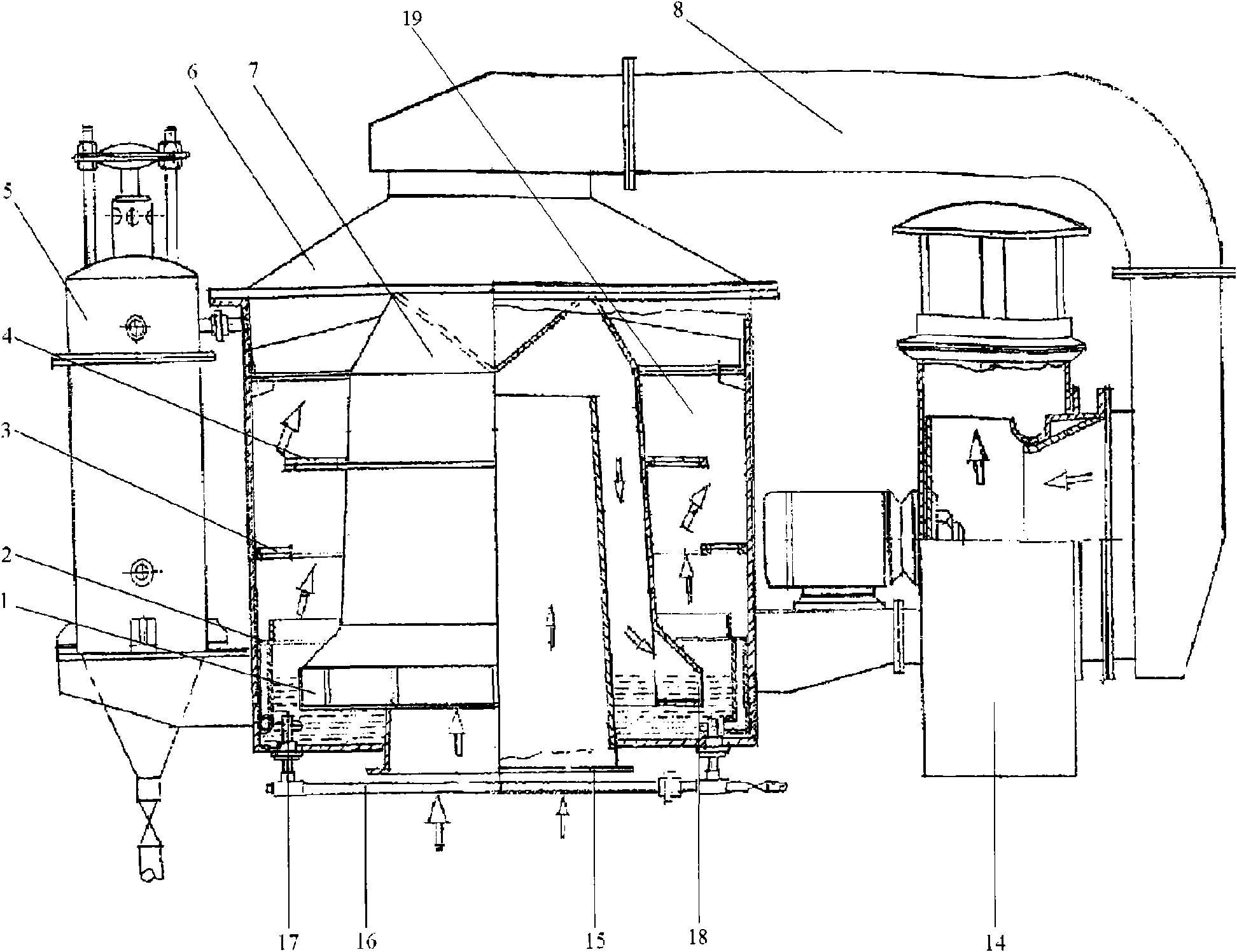
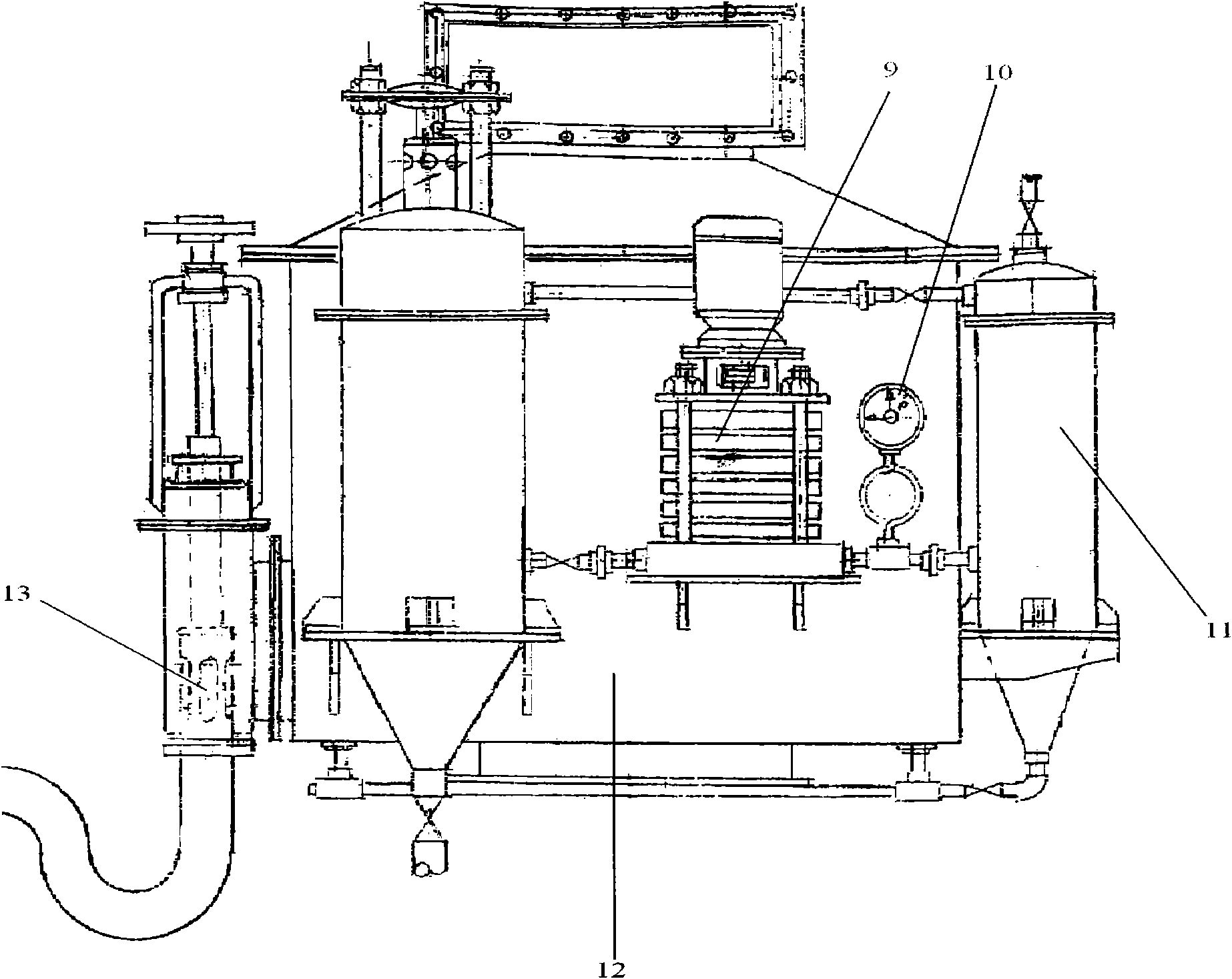
[0021] like figure 1 and image 3 As shown, it is the dust removal device of the present invention. The dust removal device includes a mixing dust chamber 7, a fan 14 and a water supply system. The mixing dust chamber 7 is connected with the fan 14 through the air duct pipeline 8 . The mixing and dust removal chamber 7 is a hollow cylinder structure, and a turbine cyclone flow dividing chamber 1 is arranged at the lower end of the cylinder structure, and the upper end of the cylinder structure shrinks slightly toward the middle and is closed. A main dust removal barrel 12 is arranged on the outside of the mixed dust removal chamber 1, and an inner dust suction pipe 15 is arranged at the lower end of the dust removal main barrel 12. The inner dust suction pipe 15 extends toward the inside of the dust removal main barrel 12 to the mixed dust removal. In the chamber 1...


PUM

PropertyMeasurementUnit
dust removal efficiencyaaaaaaaaaa

Abstract

The invention discloses a dust removing device comprising a mixed dust removing device, a fan and a water supply system, wherein the mixed dust removing device is connected with the fan by a duct pipeline, the mixed dust removing chamber is a hollow cylindrical structure, the lower end of the mixed dust removing chamber is provided with a turbo-cyclone splitting chamber, the upper end of the mixed dust removing chamber is contracted towards the middle slightly and sealed, the outer side of the mixed dust removing chamber is provided with a dust removing main barrel body, the lower end of the dust removing main barrel body is provided with an inner dust sucking duct pipe, the inner dust sucking duct pipe extends into the mixed dust removing chamber from the interior of the dust removing main barrel body, the upper end of the dust removing main barrel body is provided with an air collecting cover, and an opening is arranged at the middle of the air collecting cover and is connected with the duct pipeline to form a passage; the air collecting cover, the dust removing main barrel body, the inner dust sucking duct pipe and the mixed dust removing chamber are sequentially connected to form a cavity body, and water for removing dust is arranged in the cavity body. The dust removing efficiency of the dust removing device can reach 99.8 percent, the electricity consumption of the dust removing device is less than 1 / 3 of that of the common dust removing device, the energy conservation of the dust removing device reaches above 15 percent, and the water consumption of the dust removing device is 1 / 16 of that of the common dust removing device.

Description

technical field [0001] The invention relates to a dedusting device, in particular to a turbine rotating split siphon mixed dedusting device suitable for use in power plants, metallurgy, chemical industry, mines, wharfs, freight yards and the like. Background technique [0002] With the continuous improvement of people's quality of life, higher requirements for environmental protection have been put forward. Especially in some places with heavy pollution, such as power generation enterprises, iron and steel enterprises and petrochemical enterprises, a large amount of dust will be generated when unloading into coal, mine and other silos on the conveyor belt, which not only seriously pollutes the environment, but also Great harm to the health of workers. In the prior art, the atomized vacuum pulse dust removal device is a typical dust removal device. The combination effect is poor, the dust removal rate is only 85% after treatment, and some dust is still discharged with the a...

Claims


Application Information

Patent Timeline
Patent Type & Authority Applications(China)
IPC IPC(8): B01D47/00
Inventor 孙付江
Owner 孙付江
Learn More