High-voltage numerical control feedback type saturated reactive power compensation system

A compensation system, feedback technology, applied in reactive power compensation, reactive power adjustment/elimination/compensation and other directions, can solve the problems of grid under-compensation and over-compensation, achieve energy-saving power supply quality, ensure power supply quality, and improve reactive power The effect of the compensation effect

Inactive Publication Date: 2011-01-26
孔一诺
View PDF0 Cites 0 Cited by
  • Summary
  • Abstract
  • Description
  • Claims
  • Application Information

AI Technical Summary

Problems solved by technology

Due to the limited number of switching capacity series of reactive power compensation devices (such as 1N, 2N, 3N; N is the capacity of a single compensation capacitor), the reactive power compensation amount of each load center is usually not appropriate, but is often under-compensated or overcompensation state, so the decentralized independent compensation of multiple load centers may cause a large amount of undercompensation or a large amount of overcompensation in the entire grid

Method used


Image

  • High-voltage numerical control feedback type saturated reactive power compensation system
  • High-voltage numerical control feedback type saturated reactive power compensation system

Examples


Embodiment 1

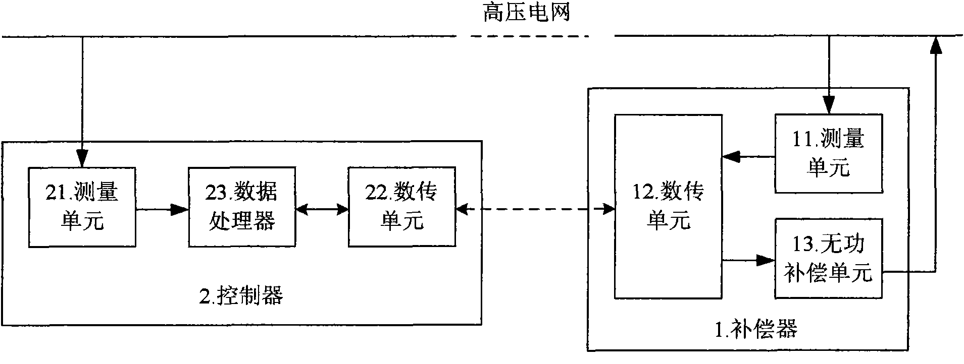
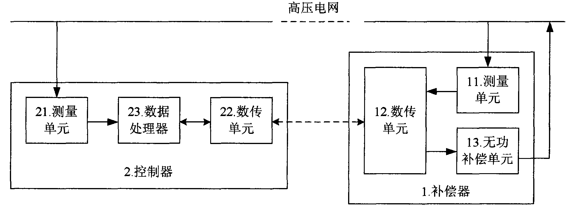
[0010] Embodiment 1: Referring to the accompanying drawings, a high-voltage numerical control feedback saturated reactive power compensation system is composed of a plurality of compensators 1 respectively arranged at each load center of the power grid, and a controller 2 arranged at the outgoing line of the substation;

[0011] The compensator 1 includes: a measurement unit 11 that samples the voltage, current, and power factor of the load center; a data transmission unit 12 that sends the sampled data to the controller 2 and accepts switching instructions from the controller 2 ; According to the switching instruction of the controller 2, the reactive power compensation unit 13 that performs multi-level compensation capacity switching;

[0012] The controller 2 includes: a measurement unit 21 that samples the voltage, current, and power factor at the outgoing line of the substation; accepts the sampled data sent by the compensator 1, and sends a digital leaflet of switching in...

Embodiment 2

[0014] Embodiment 2: In the high-voltage numerically controlled feedback type saturated reactive power compensation system described in Embodiment 1, the data processor 23, according to the sampling data of the compensator 1, provides the compensator 1 with the amount of undercompensation or overcompensation The magnitude of the amount is sorted, and the compensator 1 with a large amount of undercompensation or overcompensation is preferentially switched.


PUM


Abstract

The invention belongs to electric power equipment, and in particular relates to a power network reactive power compensation system. A high-voltage numerical control feedback type saturated reactive power compensation system consists of a plurality of compensators (1) arranged in the center of each load of a power network respectively, and a controller (2) arranged at an outgoing line of a transformer station, wherein the compensators (1) comprise a measuring unit (11) for sampling voltage, current and power factors, a data transmission unit (12) for transmitting the sampled data to the controller (2) and receiving switching commands from the controller (2), and a reactive power compensation unit (13) for executing multi-level compensation capacity switching; and the controller (2) comprises a measuring unit (21) for sampling the voltage, the current and the power factors, a data transmission unit (22) for receiving the sampled data from the compensators (1) and sending the switching commands to the compensators (1), and a data processor (23) for performing real-time monitoring and comprehensive treatment on the sampled data to form the switching commands. The high-voltage numerical control feedback type saturated reactive power compensation system can obviously improve the reactive power compensation effect on the entire power network, eliminate a large amount of phenomena of under compensation and over compensation, achieve energy conservation and ensure the power supply quality.

Description

technical field [0001] The invention belongs to electric equipment, in particular to a reactive power compensation system for a power grid. Background technique [0002] In my country's 6-35KV power grid, it is generally adopted to set up multiple independent reactive power compensation devices in multiple load centers, and determine the compensation method of switching amount of the reactive power compensation devices according to the reactive power compensation requirements of the load centers. Due to the limited number of switching capacity series of reactive power compensation devices (such as 1N, 2N, 3N; N is the capacity of a single compensation capacitor), the reactive power compensation amount of each load center is usually not appropriate, but is often under-compensated or overcompensation state, so the decentralized independent compensation of multiple load centers may cause a large amount of undercompensation or a large amount of overcompensation of the entire pow...

Claims


Application Information

Patent Timeline
Patent Type & Authority Patents(China)
IPC IPC(8): H02J3/18
CPCY02E40/30
Inventor 孔一诺
Owner 孔一诺
Why Eureka
Try Eureka