
Corner tube boiler adopting uniform scouring convection tube bundle

A technology of convective tube bundles and corner tubes, applied in steam boilers, fluid heaters, steam generation, etc., can solve the problem of high smoke velocity at high temperature end, improve heat transfer coefficient and heat transfer efficiency, improve economic benefits and reliability , the effect of wear reduction

Active Publication Date: 2009-12-09
SHANGHAI INDAL BOILER RES INST
View PDF0 Cites 5 Cited by
  • Summary
  • Abstract
  • Description
  • Claims
  • Application Information

AI Technical Summary

Problems solved by technology

People in the industry know that the amount of flue gas is proportional to the temperature of the flue gas. When the cross section of the flue is constant, the smoke velocity at both ends of the flue is very different. That is to say, when the smoke velocity at the high temperature end is within a reasonable range, the low temperature The smoke velocity at the low-temperature end is often too low; and after satisfying the smoke velocity at the low-temperature end, the smoke velocity at the high-temperature end will be too high

Method used


Image

  • Corner tube boiler adopting uniform scouring convection tube bundle
  • Corner tube boiler adopting uniform scouring convection tube bundle

Examples


Embodiment Construction

[0014] In order to better understand the technical solution of the present invention, it will be described in detail below through specific embodiments in conjunction with the accompanying drawings:

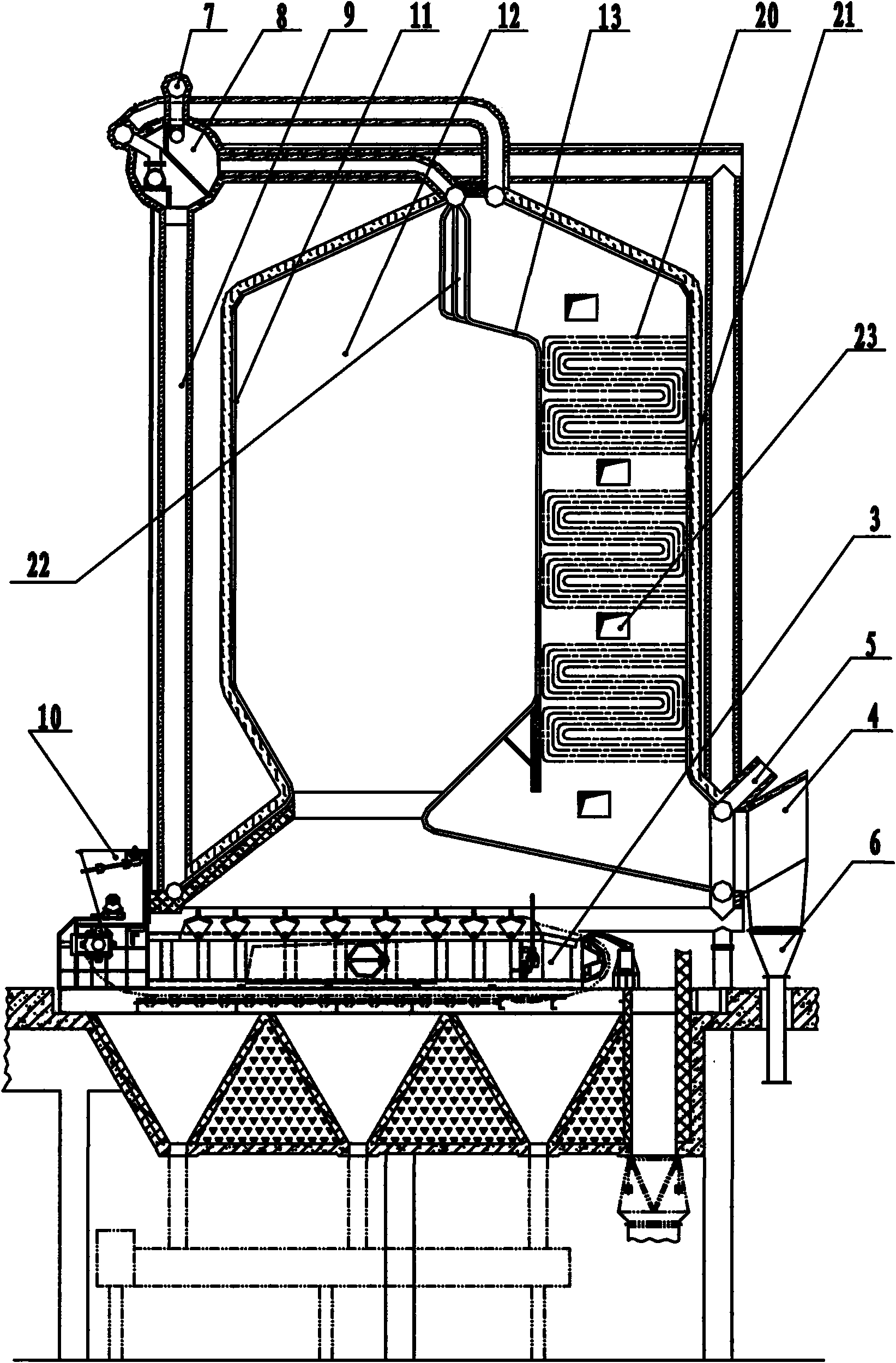
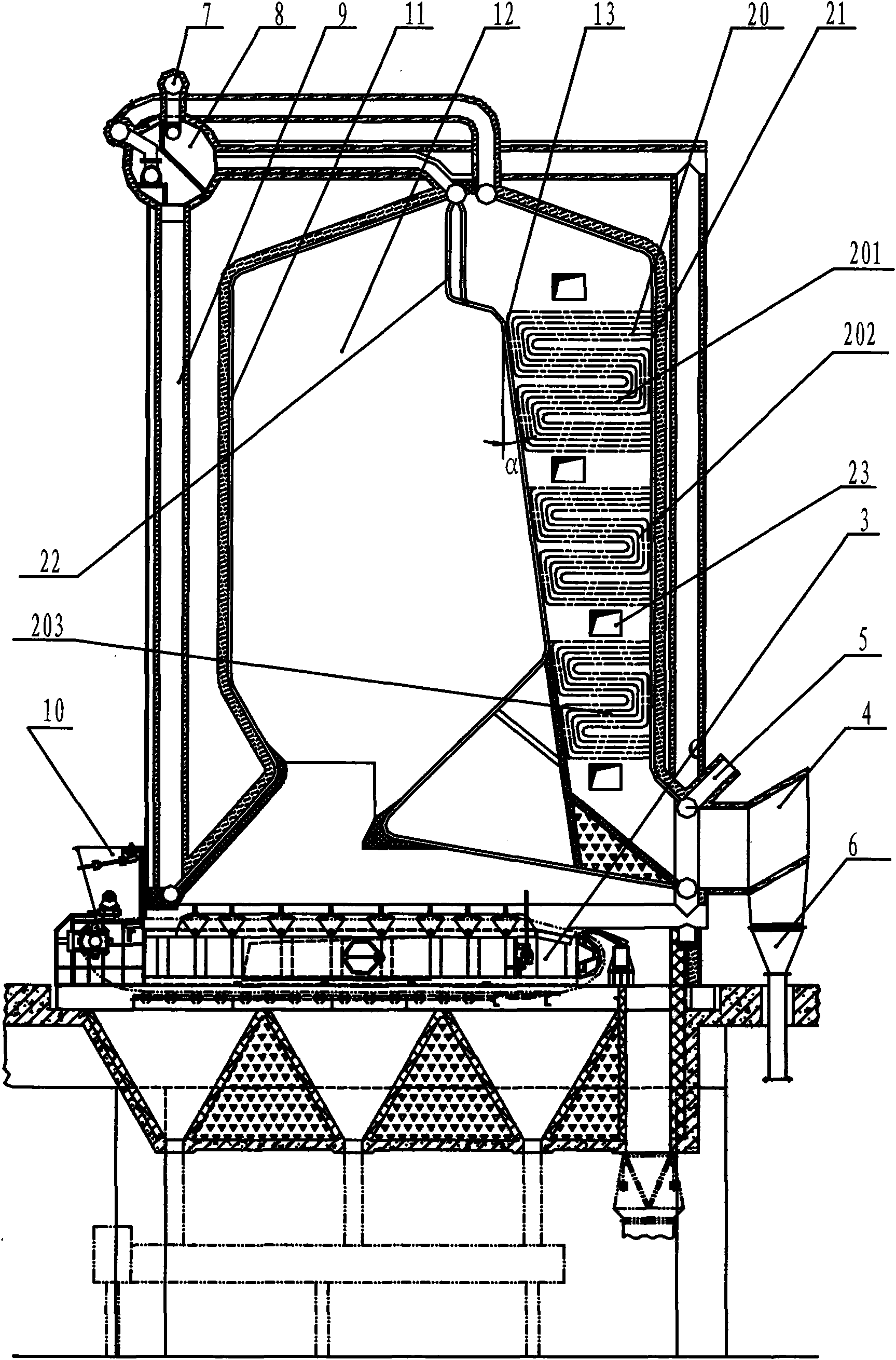
[0015] see figure 1 , the corner tube boiler in the prior art has a ∏-shaped structure as a whole, with the furnace 1 on the left and the tail flue 2 on the right, with the furnace rear wall 13 in the middle as the interface between the furnace 1 and the tail flue 2, The furnace 1 is formed by the furnace front wall 11, the side wall 12 and the furnace rear wall 13, and the tail flue 2 is formed by the furnace rear wall 13, the side wall 12 and the flue rear wall 21, wherein,

[0016] A fire grate 3 is provided at the bottom of the furnace 1; a number of convection tube bundles 20 are arranged at intervals from top to bottom in the tail flue 2, and an observation window 23 is arranged on the side wall 12 of the tail flue 2 to stagger the convection tube bundles 20; the tail flue ...


PUM


Abstract

The invention discloses a corner tube boiler adopting a uniform scouring convection tube bundle. The whole of the corner tube boiler has an n-shaped structure, wherein, the left side is a hearth, the right side is a tail flue, and the hearth back wall positioned in the middle is used as an interface of the hearth and the tail flue; the hearth front wall, the side wall and the hearth back wall form the hearth; the hearth back wall, the side wall and the flue back wall form the tail flue; the hearth front wall of the hearth is arranged vertically to the ground of the flue back wall; the hearth back wall is obliquely arranged towards the right from top to bottom so that the cross section of the hearth is gradually widened from top to bottom, and correspondingly the cross section of the tail flue is gradually narrowed from top to bottom; three sections of convection tube bundles are arranged in the tail flue from top to bottom with consistent interval to form a three-level heating surface; and the width of each section of the convection tube bundle is gradually narrowed from top to bottom and is matched with the width of the tail flue at the corresponding position. The corner tube boiler can furthest exert the heat transfer effect on the convection tube bundle under the premise of controlling the abrasion.

Description

technical field [0001] The invention relates to a corner-tube boiler adopting uniform-velocity flushing convection tube bundles. Background technique [0002] Corner tube boilers of the prior art (see figure 1 ) convection tube bundles 3 are generally placed in the rectangular tail flue 2, and the width of both sides of the furnace 1 of the boiler is generally constant, so the flue gas velocity flowing through the convection tube bundles is high at the beginning and low at the end. [0003] In heat exchange equipment such as boilers and heat exchangers, the velocity of the flue gas flowing through the convection tube bundle is a very important parameter. If the flue gas flow rate is too low, it not only reduces the heat transfer coefficient and heat transfer efficiency, but also easily precipitates the dust in the flue gas, causing dust accumulation. Severe dust accumulation will deteriorate the heat transfer, and will also cause the flue gas to block and affect the equipme...

Claims


Application Information

Patent Timeline
IPC IPC(8): F22B31/08F24H1/22
Inventor 庄祖德曹建峰吴元琦蔡晓峰陈红娟糜佳朱振声吴晓云
Owner SHANGHAI INDAL BOILER RES INST
Learn More