
Impulse turbine for use in bi-directional flows

An impingement turbine, bidirectional flow technology, applied in the direction of fluid flow, non-variable-capacity engine, engine working fluid, etc., can solve problems such as low overall efficiency

Active Publication Date: 2009-12-02
DRESSER RAND CO
View PDF2 Cites 11 Cited by
  • Summary
  • Abstract
  • Description
  • Claims
  • Application Information

AI Technical Summary

Problems solved by technology

[0007] Therefore, it is desirable to provide an alternative and provide an improved impingement turbine device that can operate from reverse bi-directional flow, such as pumped by a vibrating water column, and that provides solutions when flow through the impingement turbine A solution to the above problem of cyclically reversed time, overall inefficiency

Method used


Image

  • Impulse turbine for use in bi-directional flows
  • Impulse turbine for use in bi-directional flows
  • Impulse turbine for use in bi-directional flows

Examples


Embodiment Construction

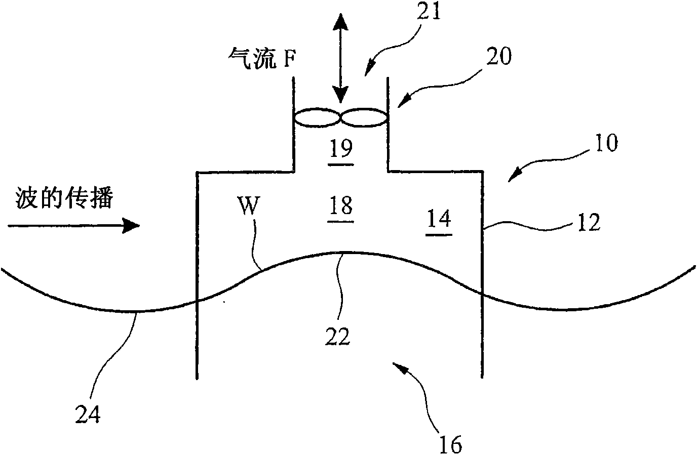
[0044] refer to figure 1 , the vibrating water column generator 10 comprises: an inverted container housing 12 defining a large, typically cylindrical chamber 14 comprising: a first opening 16 below a potential water level W; a second opening 18 ; a turbine assembly 20 mounted within the air conduit 19 ; and an outlet 21 . As the peaks 22 and troughs 24 reach the chamber 14, the level W of the water column within the chamber 14 rises and falls periodically, thereby: Alternately forcing the air within the chamber 14 through the second opening 18, past the turbine assembly 20 to the atmosphere and back through the turbine assembly 20 to draw air from the atmosphere into the chamber 14 . The bi-directional flow F through the turbine assembly 20 drives and rotates a rotor of the turbine assembly connected via a shaft to a generator to generate electricity.

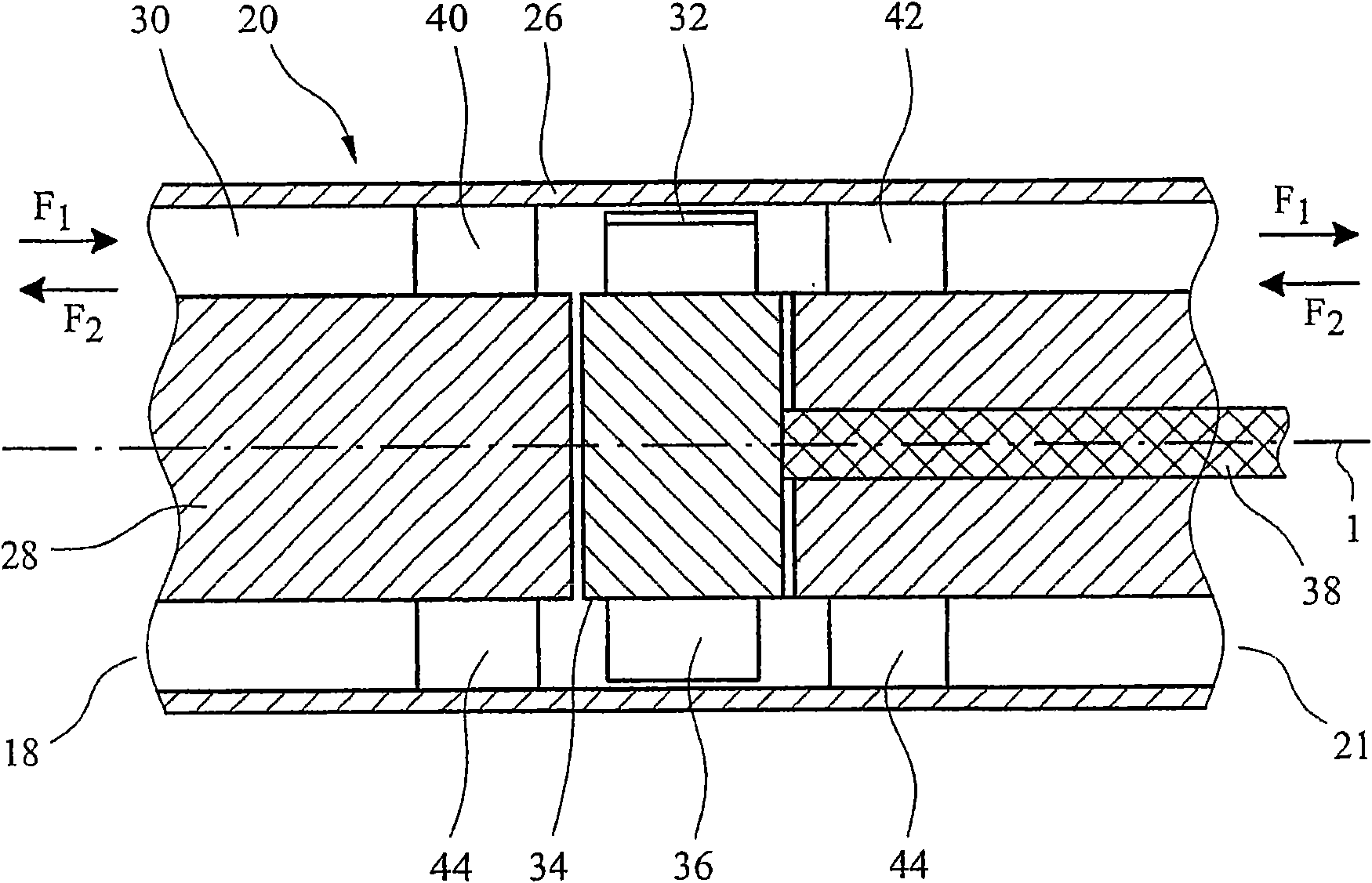
[0045] figure 2 A conventional impulse type turbine assembly 20 that may be used in such a vibrating water column genera...


PUM


Abstract

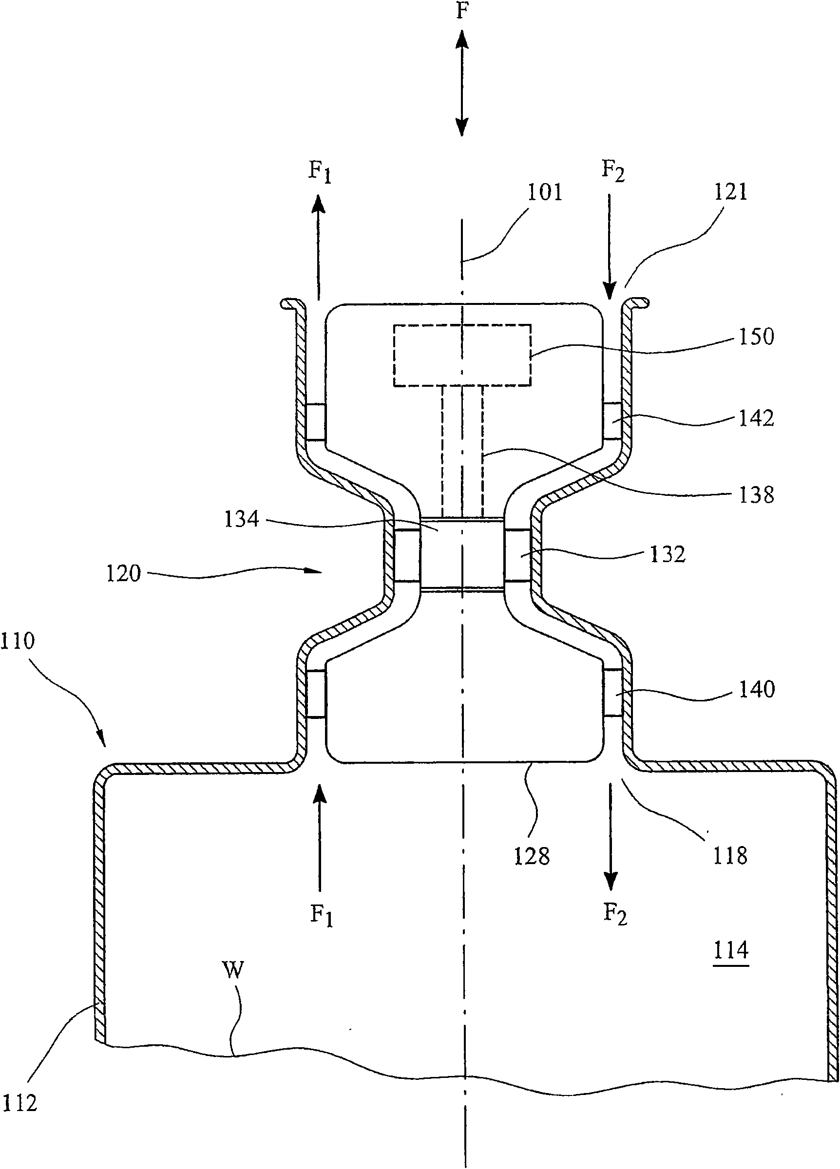
A bi-directional flow impulse type turbine arrangement (120) for use with a bi-directional reversing flow (F, F1, F2), and in particular for use with an oscillating water column power plant (110). The turbine arrangement (120) has a rotor (120), and first and second sets of guide vanes (140, 142) located on an opposite axial sides of the rotor (132) for directing the bi-directional reversing flow(F, F1, F2) to and from the rotor (132). The guide vanes (140, 142) are disposed at a greater radius (Rv) and radially offset (Ro) from the rotor blades (136). The turbine arrangement further comprises first and second annular ducts (146) disposed respectively between the first and second sets of guide vanes (140, 142) and the rotor (132) for directing fluid from the guide vanes (140, 142) to therotor blades (136). In addition, and in other aspects of the invention, the vanes (144) and rotor blades (136) have a novel profile, with in particular the vanes (144) having a profile to maintain a constant flow passage (Fp) between the vanes (144) over a turning section (164) of the vanes (144), and the rotor blades (136) of the rotor (132) having a higher turning angle (2alpha), and producing a non-axial outlet downstream flow. The turbine (120) may also in another aspect incorporate vanes (144) with a slot (190) and a boundary layer blowing arrangement to re-energise and improve the reverse flow over the vanes (144).

Description

technical field [0001] The present invention relates to turbine pack arrangements operable with bidirectional flow, and in particular to impulse turbine arrangements operable with bidirectional flow. More particularly, and preferably, it relates to a turbine arrangement for use in a vibrating water column power plant to generate electricity from wave forces. The turbine arrangement may additionally be used in the field of renewable power generation, or even more generally in other turbine applications. Background technique [0002] Generators using the power of vibrating water columns have been around for at least several decades. Typically, these generators comprise a very large chamber comprising: a first opening below potential water level; and a second opening to atmosphere via a turbine. As the crests and troughs of the waves reach the chamber, the level of the water column within the chamber rises and falls periodically, thereby alternately forcing the air in the cha...

Claims


Application Information

Patent Timeline
Patent Type & Authority Applications(China)
IPC IPC(8): F01D1/30F15D1/12F01D5/14F01D1/02F03B13/14
CPCF05D2270/17F01D5/143F05D2210/44F01D5/145F05B2240/241F05D2240/122F05D2240/304F03B13/142F05D2240/241Y02E10/38Y02E10/32F01D5/141F01D9/00F05B2210/404F05D2250/33F01D1/02F05B2250/33Y02E10/30F01D1/04F01D9/041F15D1/12F01D1/30F03B13/12F03B13/14F03B13/24
Inventor 克里斯托弗·弗里曼斯蒂芬·詹姆斯·赫里凯文·班克斯
Owner DRESSER RAND CO
Learn More