
Folding steering-wheel lock

A steering wheel lock and folding technology, which is applied in anti-theft vehicle accessories, transportation and packaging, vehicle parts, etc., can solve the problem that the guard-type car anti-theft lock cannot be removed, and the guard-type car cannot be cut by sawing. The top handle of the anti-theft lock cannot withstand the car dashboard and other problems

Inactive Publication Date: 2009-12-02
李健令
View PDF0 Cites 0 Cited by
  • Summary
  • Abstract
  • Description
  • Claims
  • Application Information

AI Technical Summary

Problems solved by technology

[0003] The guard type automobile (steering wheel) anti-theft lock that Chinese patent ZL 200520058918-8 proposes, its main difference with traditional steering wheel anti-theft lock is that the shield type automobile anti-theft lock can effectively protect the steering wheel: its U-shaped guard covers the steering wheel The spokes and the nearby outer rim are shrouded and covered, and are locked on one of the spokes of the steering wheel through a lock beam, so that thieves cannot cut off the spoke and the nearby outer rim by sawing, so they cannot remove the guard car anti-theft lock, thus solving the fatal shortcoming of the steering wheel lock: the steering wheel lock can be removed by simply sawing and cutting the steering wheel
However, the instrument panel of some models is not directly facing the steering wheel, or the instrument panel is too low, so that the top handle of the guard-type car anti-theft lock cannot withstand the car dashboard, which makes the guard-type car anti-theft lock not suitable for these models.

Method used


Image

  • Folding steering-wheel lock
  • Folding steering-wheel lock
  • Folding steering-wheel lock

Examples


Embodiment Construction

[0032] The present invention will be further described below in conjunction with accompanying drawing. However, the present invention is not limited to the following implementation examples.

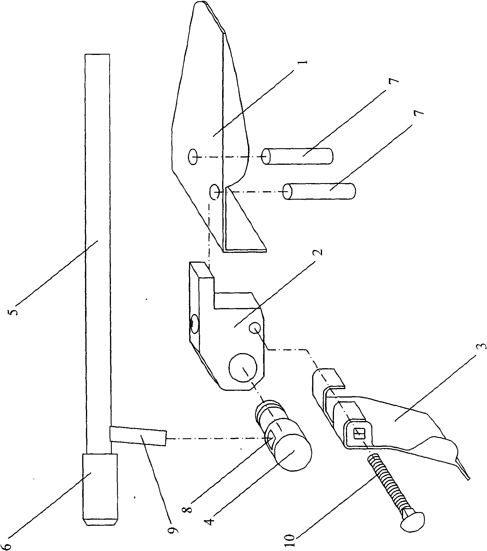
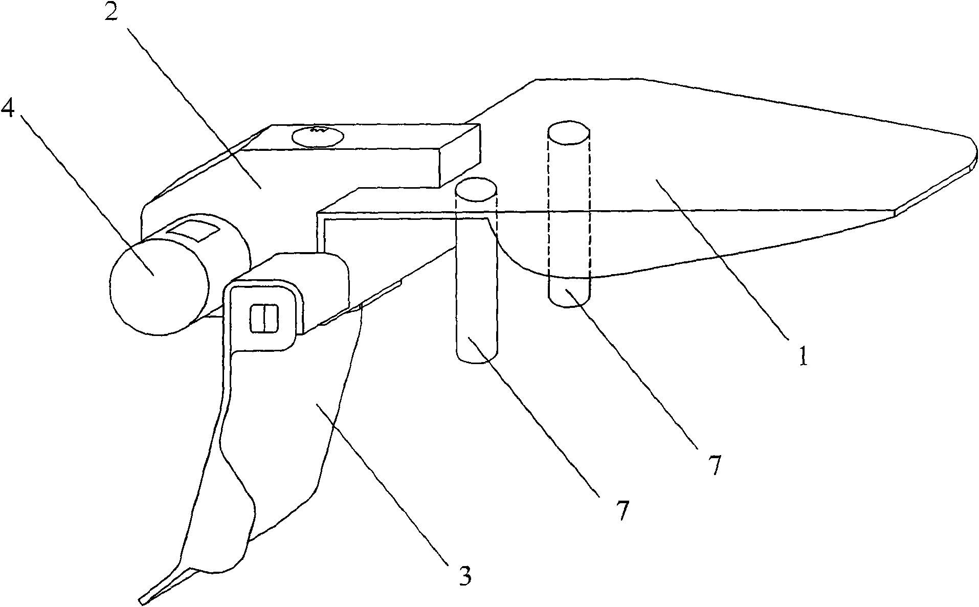
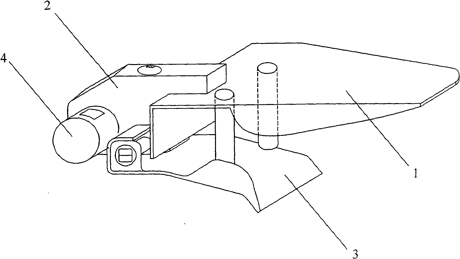
[0033] according to figure 1 As shown, the present invention is mainly composed of a front armor 1 , a pair of positioning posts 7 , a lock cylinder body 2 , a rear armor 3 , a rotating shaft 4 , a lock rod 5 and a top piece 6 . The front armor 1 is rigidly connected with the positioning post 7 and the lock cylinder body 2 . In this embodiment, the positioning post 7 is rigidly connected to the front armor 1 by welding, riveting or bolting. The rotating shaft 4 passing through the lock cylinder body 2 has a connecting hole 8, and the connecting column 9 welded on the lock rod 5 penetrates into the connecting hole 8, and then the connecting column 9 is fixed to the rotating shaft 4 with bolts or rivets. The cross section of the connecting column 9 is preferably square or rectangular, a...


PUM


Abstract

The invention relates to a folding steering-wheel lock, belonging to the theft-proof field of cars. The invention discloses a folding steering-wheel lock provided with a front protective armour and a rear protective armour, wherein the front protective armour is provided with a pair of positioning columns; the rear protective armour is connected to a hinge shaft perpendicular to a lock rod and can rotate around the hinge shaft so that the rear protective armour can be at a clamping position with the front protective armour or a opening position; when the lock rod is located at the opening position with the front protective armour, the front end of the lock rod supports against the rear protective armour, and the rear protective armour is located at the clamping position with the front protective armour and can not open. The front protective armour and the rear protective armour clamp the spoke shaft of the steering wheel; a pair of positioning columns locates the folding steering-wheel lock on the spoke shaft to protect the spoke shaft of the steering wheel horizontally so as to prevent a thief from cutting; and the folding steering-wheel lock cannot be dismounted, therefore, the theft-proof performance of the folding steering-wheel lock is greatly improved. The lock rod is not necessary to support against an instrumentation console, thereby the invention is applied to various cars.

Description

technical field [0001] The invention relates to a foldable steering wheel lock, in particular to a foldable steering wheel lock that uses front armor and rear armor to protect the steering wheel spokes front and rear, so that thieves cannot use the method of cutting the steering wheel to remove the foldable steering wheel lock. Background technique [0002] At present, most of the steering wheel locks used for automobile anti-theft in China mainly include telescopic top hook type, T-shaped clip type, baseball stick type and folding type. The telescopic top hook type steering wheel lock is welded with hooks on both ends of the telescopic steel rod. When the telescopic steel rod is extended, the hooks at both ends press against the outer rim of the steering wheel to lock it on the steering wheel. The elongated steel rod will touch the interior of the car so that the steering wheel cannot be turned to achieve the purpose of car anti-theft. The T-clip type steering wheel lock h...

Claims


Application Information

Patent Timeline
Patent Type & Authority Applications(China)
IPC IPC(8): B60R25/02B60R25/022
Inventor 李巩令
Owner 李健令
Learn More