
ZVZCS three-level DC-DC converter with two-sided passive auxiliary network

A technology of DC-DC and auxiliary network, which is applied in the direction of adjusting electrical variables, high-efficiency power electronic conversion, output power conversion devices, etc., can solve the problems of rectifier diode voltage oscillation, voltage overshoot, easy damage, etc. Overshoot, suppression of voltage oscillation and overshoot, and low component loss

Inactive Publication Date: 2011-04-27
HARBIN INST OF TECH
View PDF0 Cites 0 Cited by
  • Summary
  • Abstract
  • Description
  • Claims
  • Application Information

AI Technical Summary

Problems solved by technology

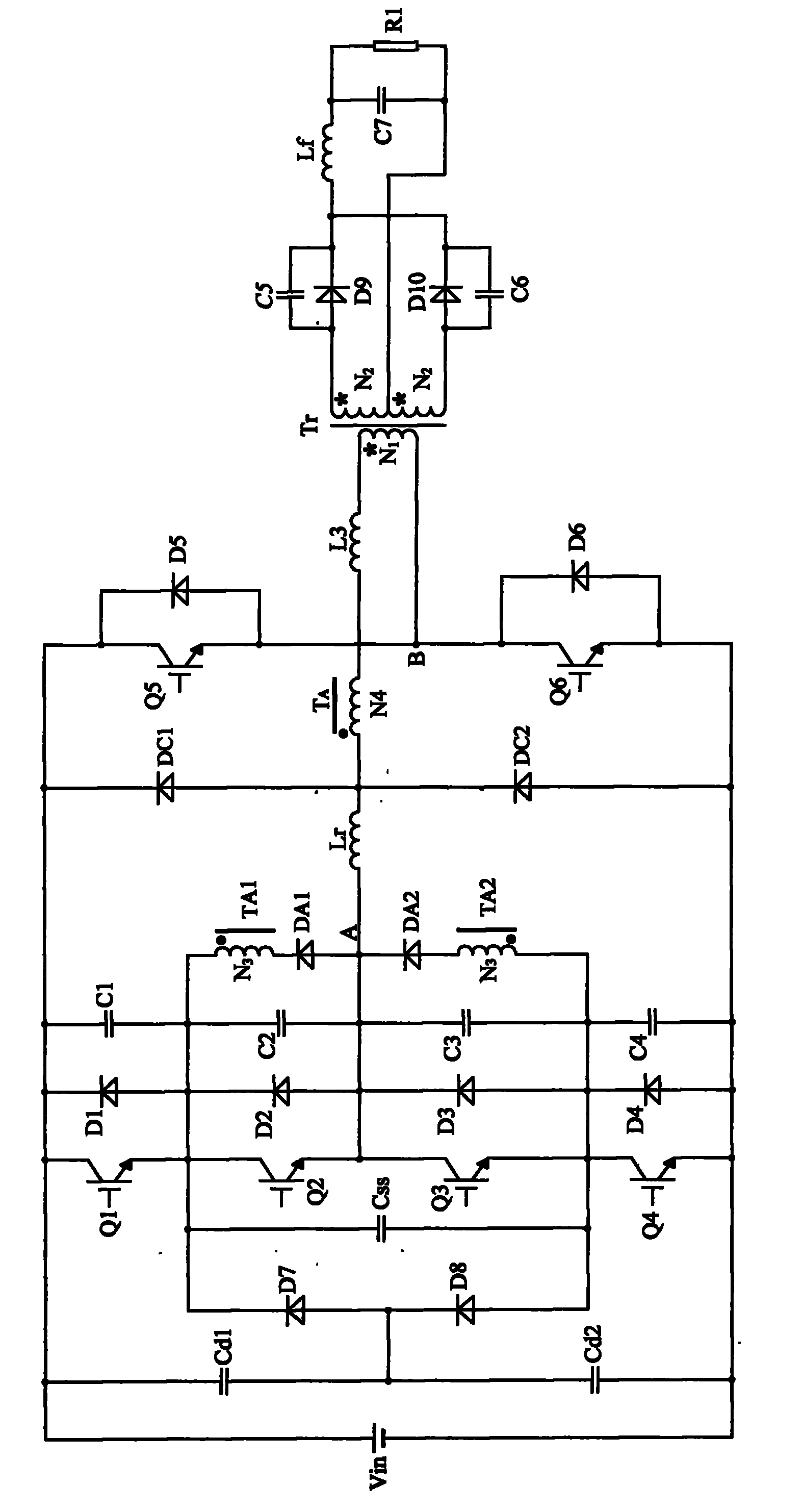
[0004] In order to enable the three-level converter to work in high-voltage and high-power occasions, and to solve the problems of voltage oscillation, voltage overshoot, and easy damage at both ends of the rectifier diode of the traditional three-level converter, the present invention proposes a double-sided non-conductive ZVZCS Three-level DC-DC Converter Based on Source Auxiliary Network

Method used


Image

  • ZVZCS three-level DC-DC converter with two-sided passive auxiliary network
  • ZVZCS three-level DC-DC converter with two-sided passive auxiliary network
  • ZVZCS three-level DC-DC converter with two-sided passive auxiliary network

Examples


specific Embodiment approach 1

[0010] Specific implementation mode one: combine figure 1Describe this embodiment, this embodiment includes the first voltage dividing capacitor Cd1, the second voltage dividing capacitor Cd2, the first diode D1 to the tenth diode D10, the first switching tube Q1 to the sixth switching tube Q6, the first One capacitor C1 to the seventh capacitor C7, the first resistor R1, the flying capacitor Css, the main transformer Tr, the third inductor L3 and the filter inductor Lf; one end of the first voltage dividing capacitor Cd1 is simultaneously connected with the positive voltage end and the first switch tube The collector of Q1, the cathode of the first diode D1, one end of the first capacitor C1, the collector of the fifth switching transistor Q5, and the cathode of the fifth diode D5 are connected; the other end of the first voltage dividing capacitor Cd1 is simultaneously It is connected with one end of the second voltage dividing capacitor Cd2, the anode of the seventh diode ...

specific Embodiment approach 2

[0075] Embodiment 2: This embodiment is described in conjunction with the drawings. The difference between this embodiment and Embodiment 1 is that a 36V / 8A experimental prototype with a switching frequency of 50kHz is designed for the converter described in the present invention. The system control circuit is based on TI's TMS320F2812 DSP, which mainly completes the drive control of the main power switch tube, provides the necessary protection for the power system, and provides the necessary calculation processing for the closed-loop of the power system.

[0076]The main power parameters of the experimental circuit are: the model selected for the first switch tube Q1 to the sixth switch tube Q6 is FGA25N120ANTD; the model selected for the rectifier diode is MUR6060PT; the auxiliary network diodes DA1, DA2, DC1, and DC2 are all selected MUR860; 1 =N 1 :N 2 =39:7; resonant inductance Lr=80μH; n 2 =N 3 :N 4 =20:18; output filter inductance Lf=160μH; output filter capacitor C...


PUM


Abstract

A ZVZCS three-level DC-DC converter with two-sided passive auxiliary network relates to a three-level converter. The aim of the invention is to cause that the three-leve converter operates in the high-voltage and large-power occasion and settle the problems of voltage oscillation, overshoot voltage and easy damage existing in the two ends of the rectifier diode of the traditional three-level converter. The anode of the voltage source is simultaneously connected with one end of a first capacitive divider, a collector of a first switching tube, a collector of a fifth switching tube, a cathode ofa first diode, a cathode of a fifth diode and one end of a first capacitor. The cathode of the voltage source is simultaneously connected with the other end of a second capacitive divider, an emitterof a fourth switching tube, an emitter of a sixth switching tube, an anode of a fourth diode, an anode of a sixth diode and the other end of the fourth capacitor. The ZVZCS three-level DC-DC converter with two-sided passive auxiliary network according to the invention furthermore comprises two auxiliary networks of a three-level side auxiliary network and a two-level side auxiliary network. The function of two auxiliary networks is providing condition for realizing zero current at the original side of the transformer and restraining the overshoot voltage at the two ends of the rectifier diode. The ZVZCS three-level DC-DC converter with two-sided passive auxiliary network according to the invention has the advantages of simple auxiliary networks, low switching loss, small overshoot voltage, small oscillation, flexible control mode, etc.

Description

technical field [0001] The invention relates to a three-level DC-DC converter, in particular to a ZVZCS three-level DC-DC converter. Background technique [0002] With the development of power electronics application technology, power conversion devices are required to develop in the direction of small size, light weight, large capacity and high efficiency. In order to meet the above requirements, it is necessary to increase the switching frequency to achieve high power density. In order to reduce the switching loss that increases with the increase of the switching frequency, the switch-mode converter technology has developed from the traditional converter to various resonant converters and various soft-switching converters. Among them, soft switching technology is considered to be the most effective way to overcome the defects of traditional converters. [0003] Commonly used single-ended circuits and bridge circuits are powerless in high-voltage and high-power workplaces...

Claims


Application Information

Patent Timeline
Patent Type & Authority Patents(China)
IPC IPC(8): H02M3/315
CPCY02B70/1491Y02B70/10
Inventor 孙铁成卢珍珍钟贵烈郭志刚郭建辉
Owner HARBIN INST OF TECH
Learn More