
Blood pressure meter

An electronic sphygmomanometer and pressure technology, applied in cardiac catheterization and other directions, can solve the problems of not guaranteeing the extraction of pulse waves, insufficient pressure, and low determination accuracy.

Active Publication Date: 2009-10-28
CITIZEN WATCH CO LTD
View PDF2 Cites 7 Cited by
  • Summary
  • Abstract
  • Description
  • Claims
  • Application Information

AI Technical Summary

Problems solved by technology

[0007] However, in the above-mentioned first electronic sphygmomanometer, due to the individual differences of the subjects, there are subjects whose reference value is appropriate and subjects whose reference value is not appropriate, so there is a judgment of insufficient pressurization. The problem of low precision
In addition, in the second electronic sphygmomanometer, after shifting to the decompression process of the cuff, it is necessary to continue the decompression until the maximum value of the pulse wave amplitude is detected, so there is a problem that the determination of insufficient pressure is limited. The time required becomes longer, which becomes the reason for forcing the testee to suffer
[0008] In addition, in the third electronic sphygmomanometer, generally, the pressurization speed is faster than the decompression speed, so it is not guaranteed that the pulse can be correctly extracted during pressurization Wave
If the extracted pulse wave is not correct, the correct threshold value cannot be obtained, so there is a problem that the judgment accuracy of insufficient pressurization is low

Method used


Image

  • Blood pressure meter
  • Blood pressure meter
  • Blood pressure meter

Examples


Embodiment Construction

[0029] Hereinafter, preferred embodiments of the electronic sphygmomanometer of the present invention will be described in detail with reference to the drawings. In addition, in the description of the following embodiments and the drawings, the same reference numerals are assigned to the same configurations, and overlapping descriptions will be omitted.

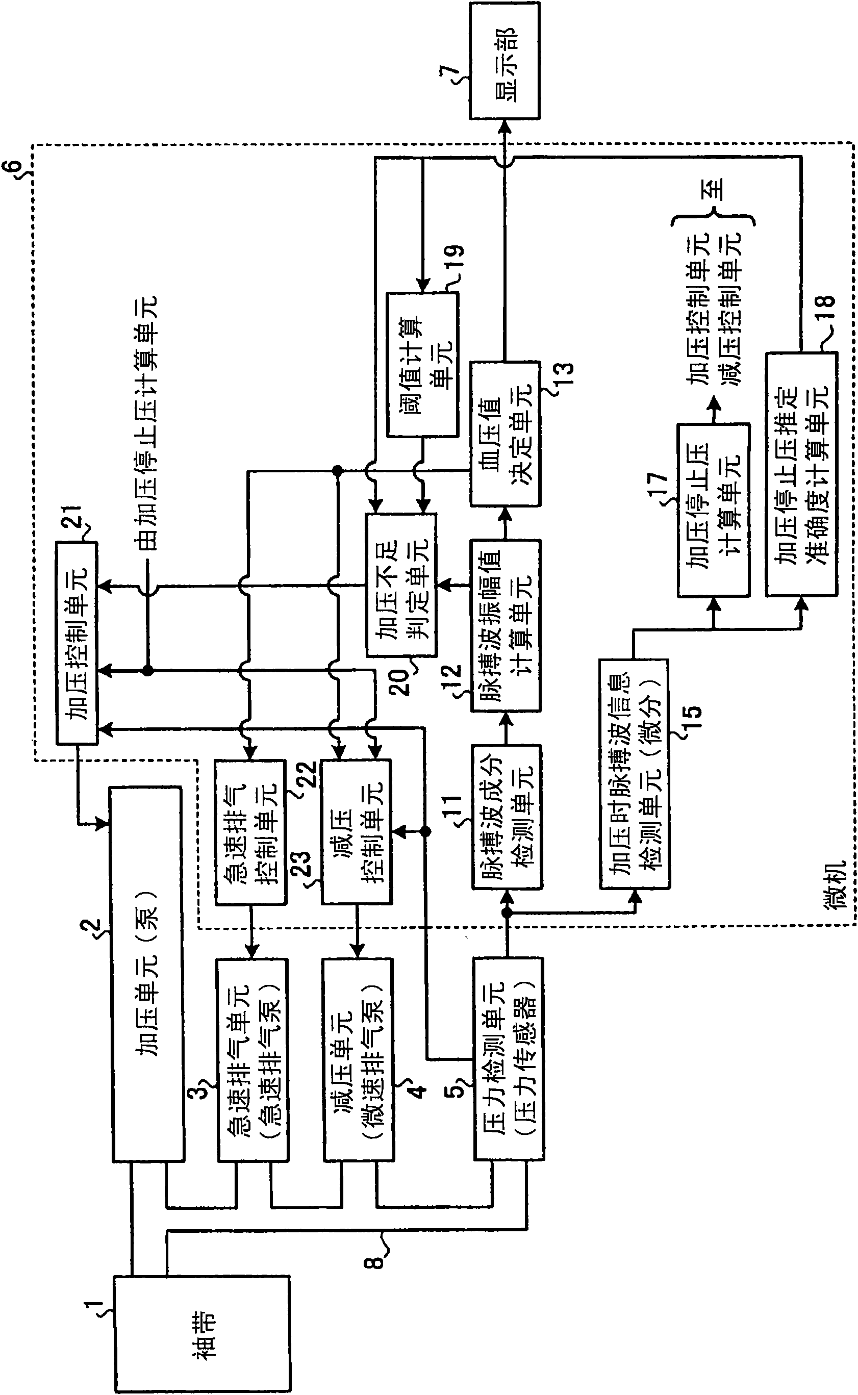
[0030] figure 1 It is a block diagram showing the configuration of the electronic sphygmomanometer according to the embodiment of the present invention. Such as figure 1 As shown, the electronic sphygmomanometer has: a cuff 1 , a pressurization unit 2 , a rapid exhaust unit 3 , a decompression unit 4 , a pressure detection unit 5 , a microcomputer (hereinafter referred to as a microcomputer) 6 , and a display unit 7 . The cuff 1 is connected with the pressurization unit 2 , the rapid exhaust unit 3 , the decompression unit 4 and the pressure detection unit 5 through a hose 8 .

[0031]The microcomputer 6 has a pressurizati...


PUM


Abstract

A blood pressure meter having a cuff (1), pressurization means (2) for pressurizing the cuff (1), depressurization means (4) for depressurizing the cuff (1), pressure detection means (5) for detecting the pressure of the cuff (1), pulse wave component detection means (11) for detecting a pulse wave component superposed on a cuff pressure signal detected by the pressure detection means (5), pulse wave amplitude calculation means (12) for calculating the value of a pulse wave amplitude from the pulse wave component detected by the pulse wave component detection means (11), and insufficient-pressurization determination means (20) for determining, when the value of a pulse wave amplitude captured at the initial stage of a depressurization process is not more than a threshold, that the cuff pressure is sufficient and determining, when the value is greater than the threshold, that the cuff pressure is insufficient. When the estimated determinacy of a pressurization stop pressure, which is calculated by means (18) for calculating the determinacy of pressurization stop pressure based on pulse wave information detected by means (15) for detecting pulse wave information at the time of pressurization, is very high, the insufficient-pressurization determination means (20) does not determine that the pressurization is insufficient. Also, the threshold is changed according to the estimated determinacy of pressurization stop pressure.

Description

technical field [0001] The present invention relates to an oscillometric electronic sphygmomanometer, and more particularly to an electronic sphygmomanometer that measures blood pressure during decompression of a cuff. Background technique [0002] Conventionally, a vibrating wave type electronic sphygmomanometer of a type that measures blood pressure while decompressing the cuff is configured to gradually pressurize the cuff to a predetermined pressure value estimated to be higher than the maximum blood pressure value. During decompression, the pressure of the cuff (hereinafter referred to as cuff pressure) is detected, and the blood pressure is determined based on the pulse wave component included in the cuff pressure signal. Therefore, even if the blood pressure is shifted to the decompression process in a state where the cuff is insufficiently pressurized, the correct blood pressure cannot be determined. Here, an electronic sphygmomanometer is proposed that has a functi...

Claims


Application Information

Patent Timeline
IPC IPC(8): A61B5/0225
CPCA61B5/0225
Inventor 伊藤清
Owner CITIZEN WATCH CO LTD
Learn More