
Signal modulation device and control method thereof

A control method and signal modulation technology, applied in the direction of pulse duration/width modulation, electrical components, amplifiers, etc., can solve problems such as switching loss, achieve the effects of reducing power loss, improving fidelity, and improving output efficiency

Inactive Publication Date: 2011-06-15
MOBILE DEVICES
View PDF0 Cites 0 Cited by
  • Summary
  • Abstract
  • Description
  • Claims
  • Application Information

AI Technical Summary

Problems solved by technology

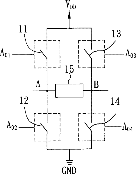
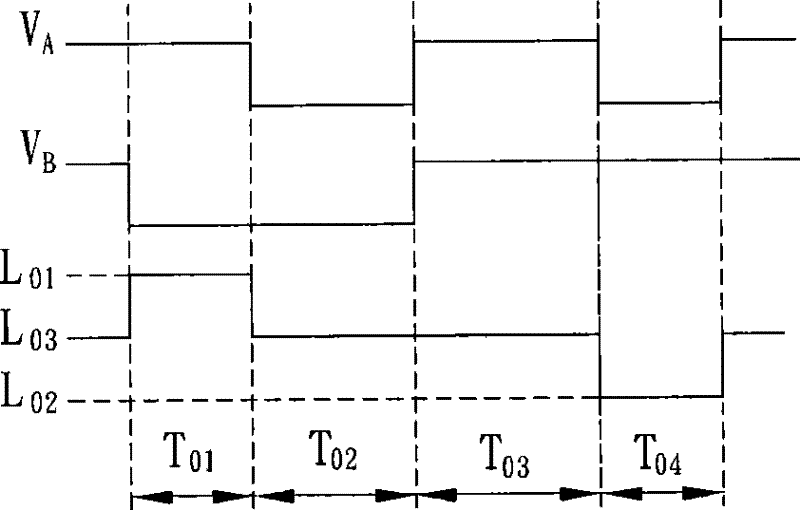
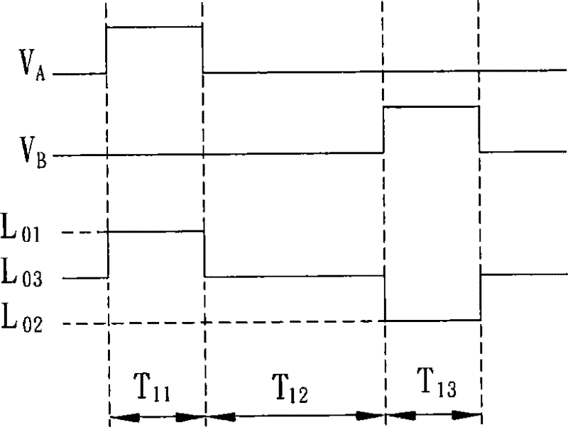
[0011] Based on the above, in general, the switching action of the switch will cause additional switching loss, and the control method of the four-element modulation has two stages of switching, both of which control the driving signal to the third level, although the three-way modulation Meta-modulation only utilizes one-stage switching, but it still incurs switching loss

Method used


Image

  • Signal modulation device and control method thereof
  • Signal modulation device and control method thereof
  • Signal modulation device and control method thereof

Examples


Embodiment Construction

[0069] The signal modulation device and its control method according to preferred embodiments of the present invention will be described below with reference to related figures.

[0070] Please refer to FIG. 4, a signal modulation device 2 of a preferred embodiment of the present invention is applied to a class D amplifier, which includes a pulse width modulation module 3, a control module 4, a switching module 5 and a Feedback module6. The pulse width modulation module 3 , the control module 4 and the feedback module 6 are electrically connected to each other, and the switching module 5 is electrically connected to the control module 4 and the feedback module 6 respectively. In this embodiment, the control module 4 can be a microcontroller or a processor.

[0071] The pulse width modulation module 3 receives a data signal and outputs a first pulse width modulation signal A P1 and a second PWM signal A P2 , where the data signal has a positive period data A 1 and a negativ...


PUM


Abstract

The invention relates to a signal modulation device comprising a pulse width modulation module, a control module, a switching module and a feedback module, wherein the pulse width modulation module receives a data signal, and generates a first pulse width modulation signal and a second pulse width modulation signal according to the data signal and the feedback signal. The control module is electrically connected with the pulse width modulation module and generates a first switching control signal and a second switching control signal according to the first pulse width modulation signal and thesecond pulse width modulation signal. The switching module is electrically connected with the control module and outputs a driving signal to drive a load according to the first switching control signal and the second switching control signal. The feedback module is respectively electrically connected with the pulse width modulation module, the control module and the switching module, and generates and transmits a feedback signal to the pulse width modulation module according to the switching state of the switching module.

Description

technical field [0001] The invention relates to a signal modulating device and a control method thereof. Background technique [0002] Generally speaking, signal modulation devices applied to audio systems are roughly divided into class A and class AB amplifiers, which directly output analog audio signals to drive speakers. [0003] Recently, Class D amplifiers with lower power consumption have gradually replaced the applications of Class A and Class AB amplifiers. The class D amplifier mainly modulates an analog audio signal into a pulse signal, outputs a switching signal through a switching module, and then converts it into an analog driving signal through a filter to drive a speaker. With the advancement of technology, a filterless class D amplifier (class D filterless amplifier) ​​has also been developed recently, that is, a switching signal is used as a driving signal to directly drive a speaker. [0004] In switching modules for Class D amplifiers, such as figure 1 ...

Claims


Application Information

Patent Timeline
Patent Type & Authority Patents(China)
IPC IPC(8): H03F3/217H03K7/08
Inventor 许浚伟
Owner MOBILE DEVICES
Learn More