Fluid pump driven by compressed air

A technology for compressing air and fluid pumps, which is applied to pumps, piston pumps, machines/engines, etc., and can solve problems such as difficult, easy-to-failure maintenance and installation of pistons, and achieve the effect of simple maintenance and installation

Inactive Publication Date: 2010-08-18
赵宽学
View PDF0 Cites 1 Cited by
  • Summary
  • Abstract
  • Description
  • Claims
  • Application Information

AI Technical Summary

Problems solved by technology

[0003] In order to solve the problems in the prior art that the piston is easy to fail and difficult to repair and install, the present invention provides a fluid pump driven by compressed air

Method used


Image

  • Fluid pump driven by compressed air
  • Fluid pump driven by compressed air
  • Fluid pump driven by compressed air

Examples


Embodiment Construction

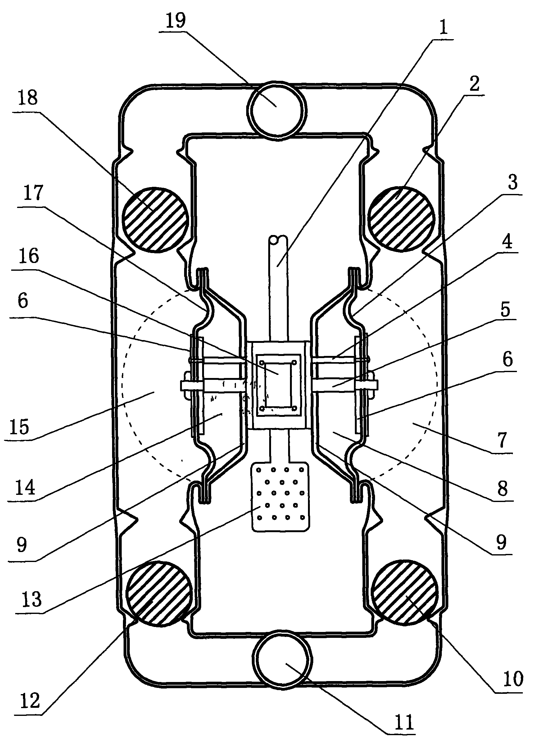
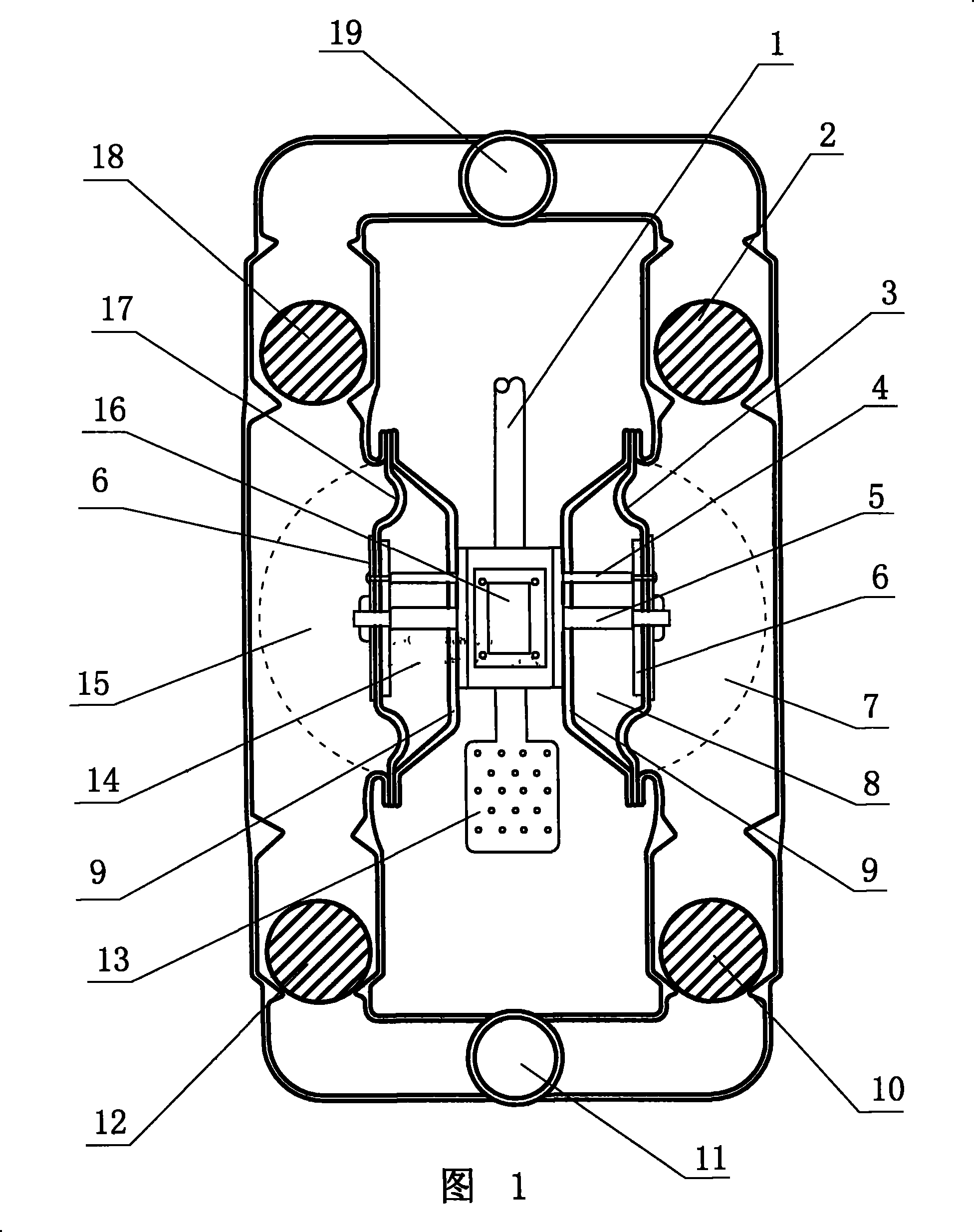
[0056] As shown in Figure 1, Figure 2, and Figure 3, a fluid pump driven by compressed air includes a central body 16, a central shaft 5, a reversing shaft 4, a left diaphragm 17, a right diaphragm 3, and a left air chamber 14. , Right air chamber 8, left fluid chamber 15, right fluid chamber 7, valve ball A18, valve ball B2, valve ball C12, valve ball D10, fluid inlet 11 and flow outlet 19 and so on. The central shaft 5 and the reversing shaft 4 are movably mounted on the central body 16, a sealing ring is installed between the central shaft 5, the reversing shaft 4 and the central body 16, and the central shaft 5 and the reversing shaft 4 move left and right on the central body 16. When the air will not pass. The left diaphragm 17 and the right diaphragm 3 are respectively installed at both ends of the central shaft 5. The two diaphragms are fixed on the two ends of the central shaft 5 by the diaphragm clamping plate 6. The two ends of the reversing shaft 4 are also connected...


PUM


Abstract

A fluid pump driven by compressed air comprises a central body, a central shaft, a reversing shaft, membranes, air chambers, fluid chambers, a valve ball, a fluid inlet, a fluid outlet, etc. The central shaft and the reversing shaft are installed on the central body; a membrane is respectively installed at the two ends of the central shaft; the membranes are fixed at the two ends of the central shaft by membrane splints; and the two ends of the reversing shaft are also respectively connected on a left membrane splint and a right membrane splint. The membranes are clamped between a shell and apump body; and the two membranes are sealed into a left air chamber, a right air chamber, a left fluid chamber and a right fluid chamber between the shell and the pump body; the reversing shaft controls the horizontal movement of a piston and respectively charges the two air chambers, and pushes and presses the fluid chambers by the membranes to lead the fluid to flow from the fluid inlet into thefluid chambers and then out of the fluid outlet. As the fluid pump which is driven by compressed air is provided with the reversing shaft, the movement of the piston is directly controlled by the compressed air but does not fail, and the maintenance and installation are convenient.

Description

Technical field [0001] The invention relates to a fluid pump, in particular to a fluid pump driven by compressed air. Background technique [0002] Pneumatic fluid pump is a fluid delivery pump with compressed air as energy source. The main structure of pneumatic fluid pump includes air valve, diaphragm, central shaft, shell, valve ball, fluid inlet and fluid outlet. The central shaft can slide left and right on the central body. A diaphragm is installed at both ends of the central shaft. The diaphragm is fixed in the shell. The two diaphragms are sealed in the shell into two left and right air chambers and two left and right fluid chambers. The left and right air chambers alternately supply and exhaust air under the action of the air valve. When the air valve supplies air to the left air chamber, the left diaphragm expands outward to push the left fluid chamber, and the fluid in the left fluid chamber pushes upward The valve opening ball is output from the outlet. At the same t...

Claims


Application Information

Patent Timeline
Patent Type & Authority Patents(China)
IPC IPC(8): F04B9/129
Inventor 赵宽学
Owner 赵宽学
Why Eureka
Try Eureka