Card conveying mechanism and card guider

A card handling mechanism and card technology, applied in the directions of transportation and packaging, instruments, computer parts, etc., can solve the problem of preventing the co-rotation of the rotating shaft and the rotating parts, and achieve the effect of preventing co-rotation.

Active Publication Date: 2009-09-30
SANKYO SEIKI MFG CO LTD
View PDF6 Cites 5 Cited by
  • Summary
  • Abstract
  • Description
  • Claims
  • Application Information

AI Technical Summary

Problems solved by technology

However, in the card conveying device described in Patent Document 1, there is no device for preventing the rotating shaft from co-rotating with the rotating member.

Method used


Image

  • Card conveying mechanism and card guider
  • Card conveying mechanism and card guider
  • Card conveying mechanism and card guider

Examples


other Embodiment approach

[0066] The above-mentioned embodiment is an example of a preferable embodiment of the present invention, but it is not limited thereto, and various modifications can be made without changing the gist of the present invention.

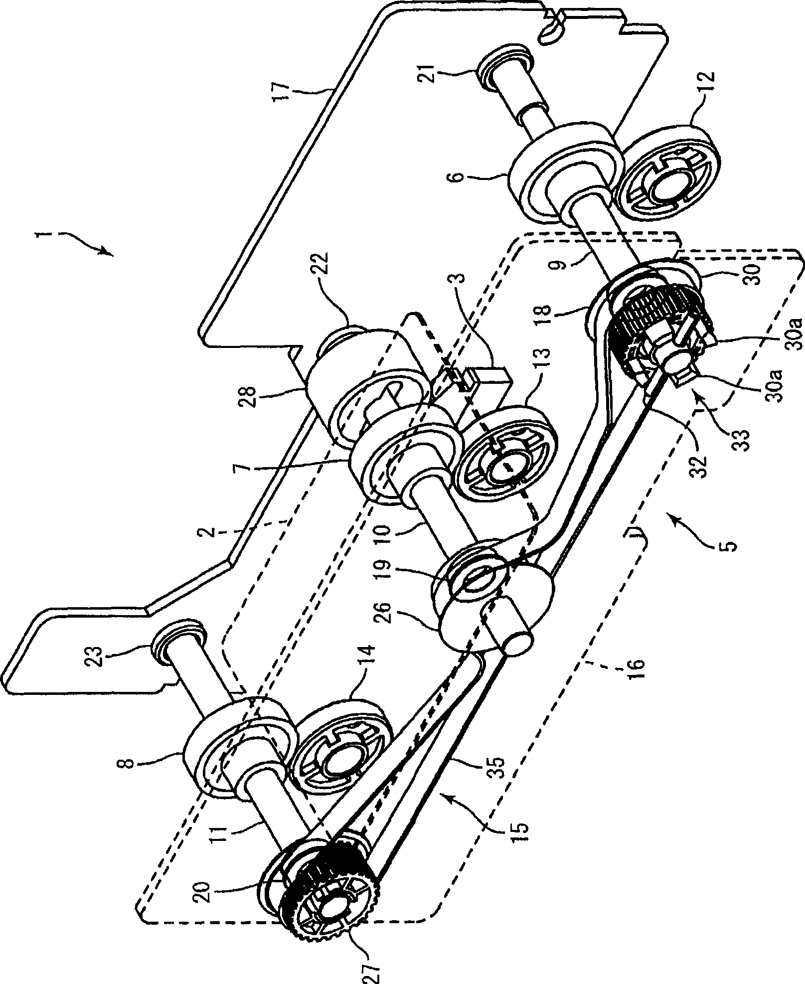
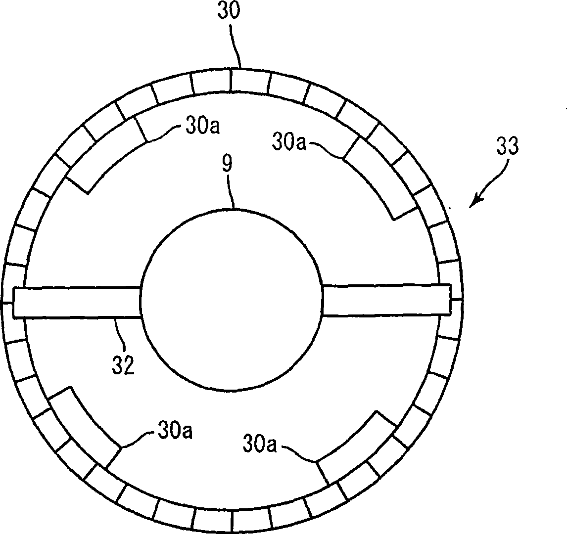
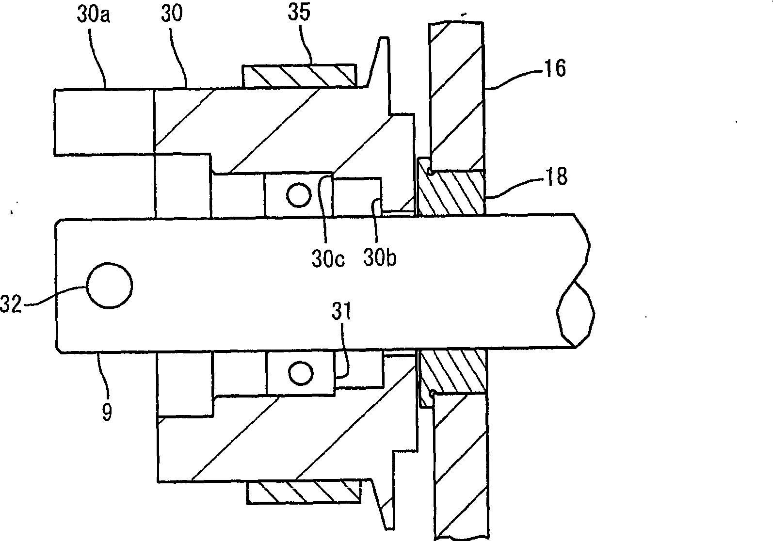
[0067] In the above-described embodiment, the bearing 21 is a sliding bearing like the bearing 18 . Besides, the bearing 21 may also be a rolling bearing, for example. Even in this case, since the bearing 18 disposed near the pulley 30 is a sliding bearing, it is possible to prevent the shaft 9 from co-rotating with the pulley 30 when power transmission is cut off by the clutch mechanism 33 . In addition, the bearings 19, 20, 22, and 23 may also be rolling bearings.

[0068] In the above-described embodiment, the rotating shaft 9 is supported at two locations by the bearings 18 , 21 . In addition, for example, the rotating shaft 9 may be supported at three or more locations using bearings or the like. In this case, if at least the bearing disposed cl...


PUM


Abstract

A card conveying mechanism and a card guider can prevent the co-rotation of the rotating shaft and the rotating component when the power transmission is cut off by a clutch mechanism. The card conveying mechanism (5) of the conveying card (2) comprises the following components: a conveying roller (6) which abuts against the card (2) for conveying the card (2), a rotating shaft (9) which is fixed with a conveying roller (6), a rotating component (30) which is rotatably supported by the rotating shaft (9), a driving mechanism (15) which is connected with the rotating component (30) and rotates the rotating component (30), and a clutch mechanism (33) which connects or cuts off the power transmission between the rotating shaft (9) and the rotating component (30). The rotating component (30) uses a rolling bearing for being rotatablely supported on the rotating shaft (9). The rotating shaft (9) is rotatablely supported by a plurality of bearings (18, 21). Furthermore, at least a bearing (18) which is configured closest to the rotating component (30) is a sliding bearing.

Description

technical field [0001] The present invention relates to a card conveying mechanism for conveying cards and a card guide including the card conveying mechanism. Background technique [0002] Conventionally, there is known a card transport device for transporting cards inside a card guide (for example, refer to Patent Document 1). The card transport device described in Patent Document 1 includes a feed roller for conveying cards, a shaft for fixing the feed roller, a rotating member rotatably attached to the shaft, and a drive mechanism for rotating the rotating member. [0003] In addition, the card conveying device further includes a clutch device for disconnecting the feed roller fixed to the rotating shaft from the driving mechanism so as to be freely rotatable. The clutch device includes: a pin fixed on a rotating shaft, and two engagement protrusions formed on a rotating member. Two engaging protrusions are formed on the outer surface of the rotating member in a circum...

Claims


Application Information

Patent Timeline
Patent Type & Authority Applications(China)
IPC IPC(8): B65H5/06B65H29/20G06K13/07
Inventor 平林昌彦小口胜章
Owner SANKYO SEIKI MFG CO LTD
Why Eureka
Try Eureka