
Electronic sphygmomanometer

An electronic sphygmomanometer and pressure technology, applied in the direction of cardiac catheterization, etc., can solve the problems of longer blood pressure measurement end time, unable to detect pulse wave immediately, etc., and achieve the effect of preventing the measurement time from becoming longer

Active Publication Date: 2011-04-13
CITIZEN WATCH CO LTD
View PDF1 Cites 0 Cited by
  • Summary
  • Abstract
  • Description
  • Claims
  • Application Information

AI Technical Summary

Problems solved by technology

[0005] However, with the above-mentioned existing electronic sphygmomanometer, the control initial value of the electromagnetic valve is a fixed value, so for example, when the user's physique greatly deviates from the average level, or the electromagnetic valve changes over time, or there are individual electromagnetic valves. differences, etc., tend to cause the cuff to start decompressing at a rate above or below the target decompression rate
When the cuff starts decompression at a speed higher than the target decompression speed, there are problems that the pulse wave cannot be detected immediately after the decompression starts; and when the cuff starts decompression at a speed lower than the target decompression speed, There is a problem that the time required for the end of the blood pressure measurement becomes longer

Method used


Image

  • Electronic sphygmomanometer
  • Electronic sphygmomanometer
  • Electronic sphygmomanometer

Examples


Embodiment approach 1

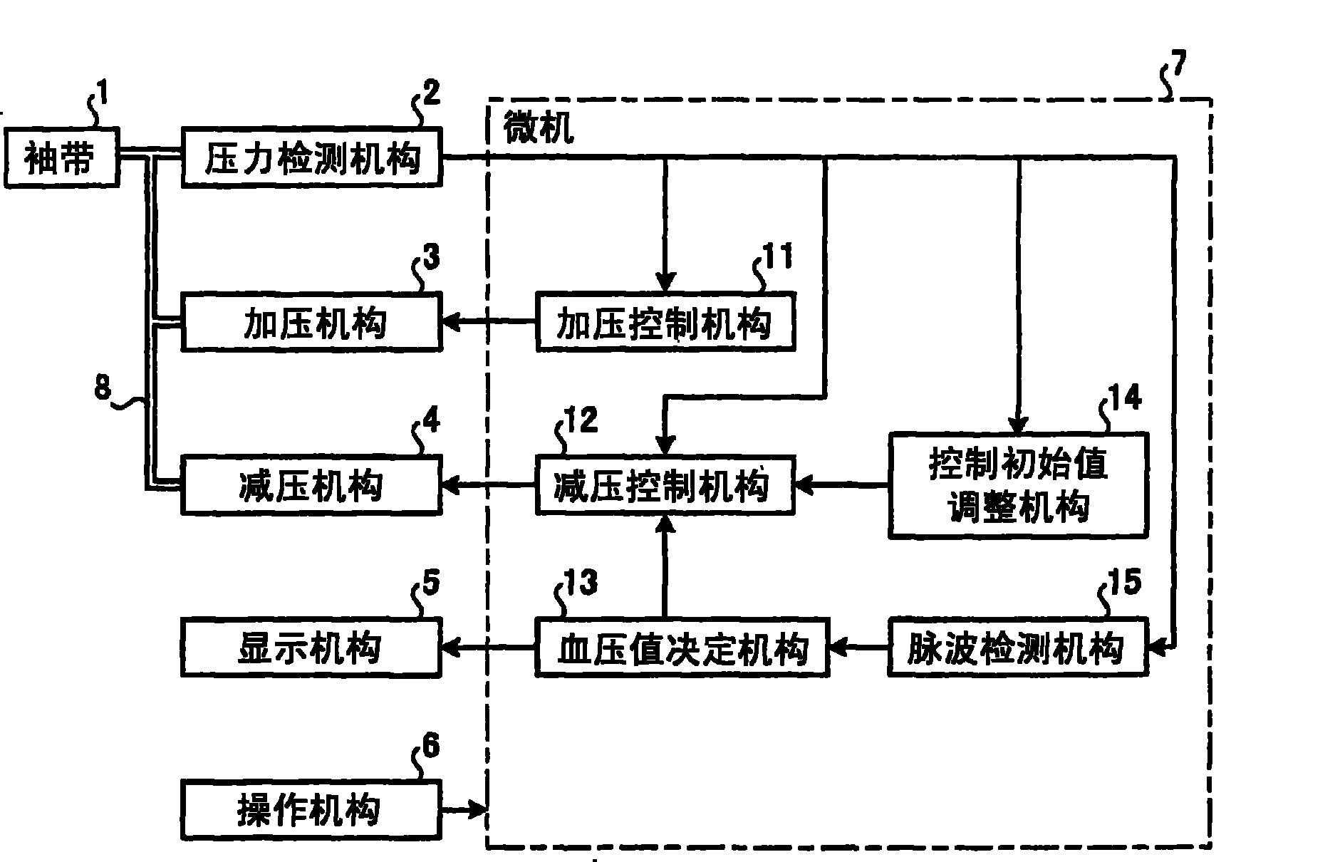
[0027] figure 1 It is a block diagram showing the overall configuration of the electronic sphygmomanometer according to Embodiment 1 of the present invention. Such as figure 1 As shown, the electronic sphygmomanometer includes: a cuff 1, a pressure detection mechanism 2, a pressurizing mechanism 3, a decompression mechanism 4, a display mechanism 5, an operating mechanism 6 and a microcomputer (hereinafter referred to as a microcomputer) 7. The cuff 1 is connected with the pressure detection mechanism 2 , the pressurization mechanism 3 and the decompression mechanism 4 through a conduit 8 .

[0028] The pressure detection mechanism 2 detects the pressure inside the cuff 1 . The pressure detection mechanism 2 is constituted by, for example, a pressure sensor. The pressurizing mechanism 3 pressurizes the cuff 1 according to the output signal of the microcomputer 7 . The pressurizing mechanism 3 is constituted by, for example, a pump that sends a fluid such as air (hereinafte...

Embodiment approach 2

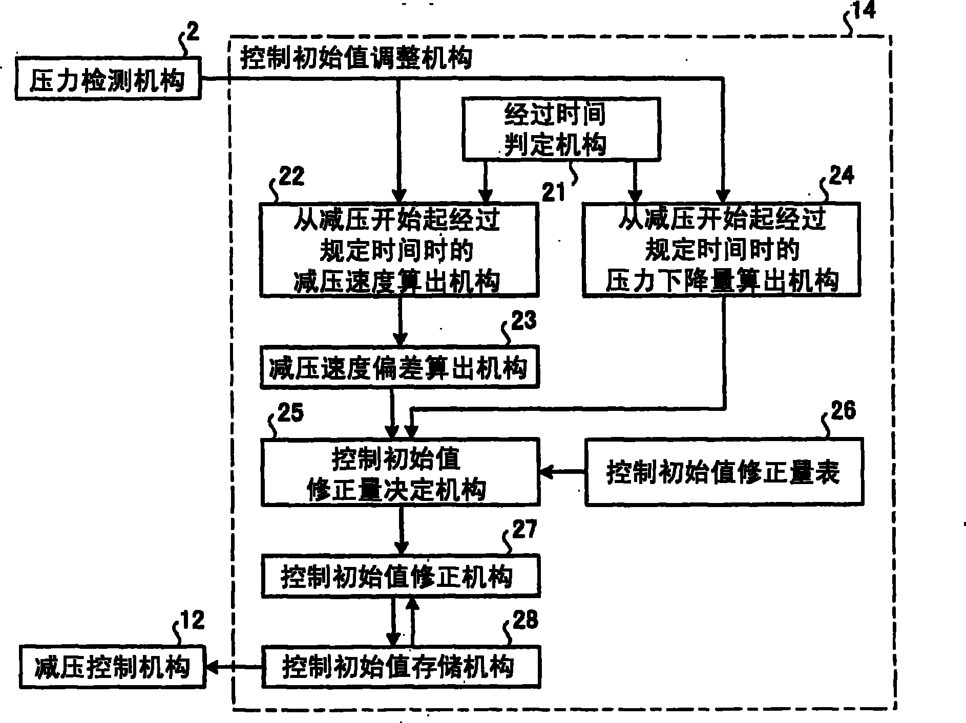
[0059] Embodiment 2 is a proposal to correct the control initial value based on the time required for the decompression speed of the cuff to reach the target decompression speed and the pressure drop amount of the cuff. The overall composition of the sphygmomanometer and figure 1 The shown configurations are the same, so descriptions are omitted. However, in the following description, since the configuration of the control initial value adjustment mechanism is different from that of Embodiment 1, the reference numeral of the control initial value adjustment mechanism is "34".

[0060] Figure 7 It is a block diagram showing the configuration of the control initial value adjustment mechanism of the electronic sphygmomanometer according to Embodiment 2 of the present invention. Such as Figure 7 As shown, the control initial value adjustment mechanism 34 includes: a decompression speed calculation mechanism 41, a decompression speed deviation calculation mechanism 42, a targe...


PUM


Abstract

The invention provides an electronic sphygmomanometer. When a pressure in a cuff (1) is decreased by a pressure-decreasing means (4), the pressure in the cuff (1) is detected by a pressure detection means (2). A control initial value adjusting means (14) adjusts the control initial value for starting pressure decreasing for the next measurement of blood pressure according to the detected pressure in the cuff (1). When the pressure decreasing of the cuff (1) is started during the next measurement of blood pressure, the opening degree of the exhaust valve of the pressure-decreasing means (4) is controlled according to the control initial value adjusted during the pressure decreasing for the present measurement of blood pressure.

Description

technical field [0001] The invention relates to an electronic sphygmomanometer, in particular to an electronic sphygmomanometer for measuring blood pressure during pressure decompression in a cuff. Background technique [0002] As an electronic sphygmomanometer, there is a method of measuring blood pressure while gradually reducing the pressure inside the cuff (hereinafter referred to as cuff pressure). Electronic sphygmomanometers of this type are usually configured to control the opening degree of the exhaust valve composed of a solenoid valve connected to the cuff when the air in the cuff is discharged, so that the decompression speed of the cuff becomes the desired one. speed. Generally speaking, the closing force of the solenoid valve is determined by the control value of the solenoid valve opening and the power supply voltage. Conventionally, the initial value of the control value (hereinafter referred to as the initial control value) is fixed at a state where a user...

Claims


Application Information

Patent Timeline
Patent Type & Authority Patents(China)
IPC IPC(8): A61B5/0225
CPCA61B5/0225
Inventor 伊藤清中西孝
Owner CITIZEN WATCH CO LTD
Learn More