
Folded waveguide filter

A waveguide filter and folded technology, which is applied to waveguide devices, electrical components, circuits, etc., can solve the problems of increasing the space occupied by the filter plane, inconvenient circuit system integration, and large plane space, so as to reduce the plane space and improve Out-of-band rejection, easy integration of effects

Active Publication Date: 2009-09-02
鄄城旭阳实业有限公司
View PDF0 Cites 9 Cited by
  • Summary
  • Abstract
  • Description
  • Claims
  • Application Information

AI Technical Summary

Problems solved by technology

[0002] The currently known waveguide filters all achieve cavity coupling on a single plane, that is, a single-layer waveguide filter. All resonators of this filter are on the same plane. Many, when the cavity of a single resonant cavity is large, it will occupy a large plane space
Therefore, this structure in the prior art not only increases the plane occupied space of the filter, but also causes inconvenience to the integration of the circuit system

Method used


Image

  • Folded waveguide filter
  • Folded waveguide filter
  • Folded waveguide filter

Examples


Embodiment 1

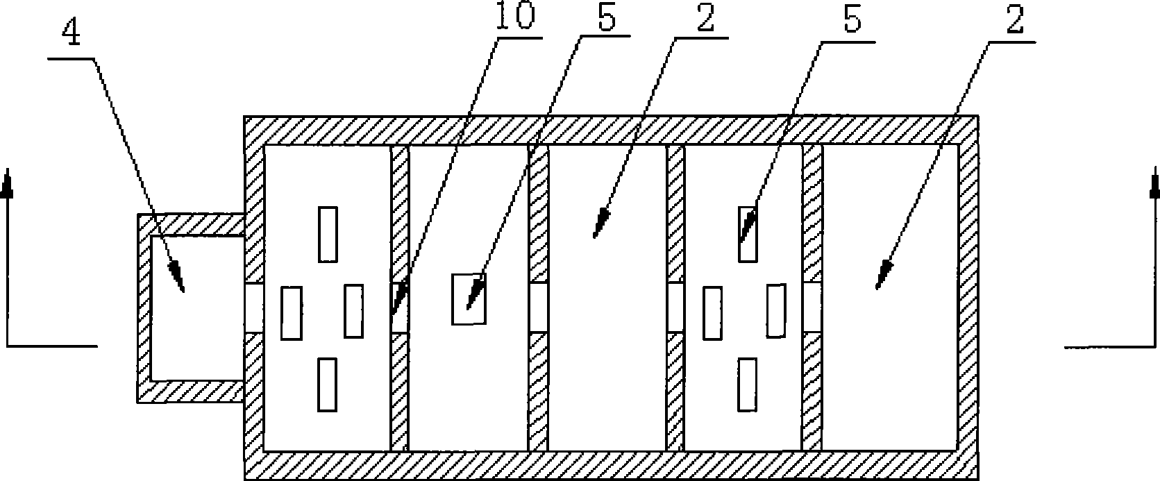
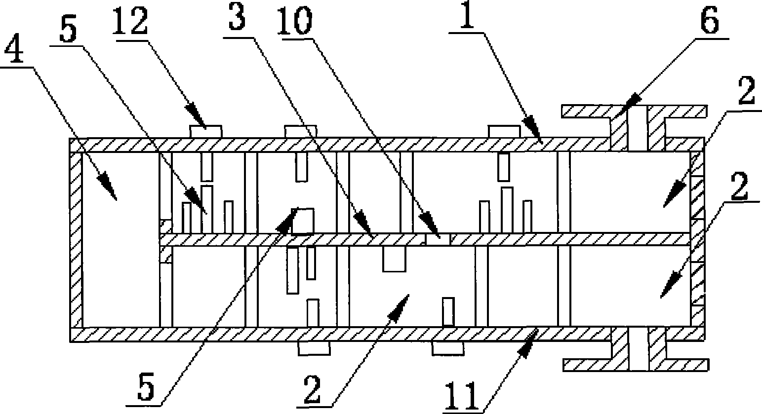
[0032] Such as figure 1 , figure 2 As shown, the folded waveguide filter includes an upper body of the filter, a lower body of the filter, a partition 3 and a connection structure 4, the upper body of the filter and the lower body of the filter are both rectangular, and the partition 3 is arranged on the filter Between the upper body of the device and the lower body of the filter; the connecting structure 4 is a rectangular cavity with one side fully open, which is arranged at the same end of the upper body of the filter and the lower body of the filter, and connects the two, so that A microwave signal path is formed between them.

[0033] In the upper body of the filter, several resonant cavities 2 are arranged between the upper cover plate 1 and the partition 3, and adjacent resonant cavities 2 are separated by metal sheets. Resonant columns 5 can be arranged inside the resonant cavity 2, or If not provided, adjacent resonant cavities 2 are connected by coupling holes 10 ...

Embodiment 2

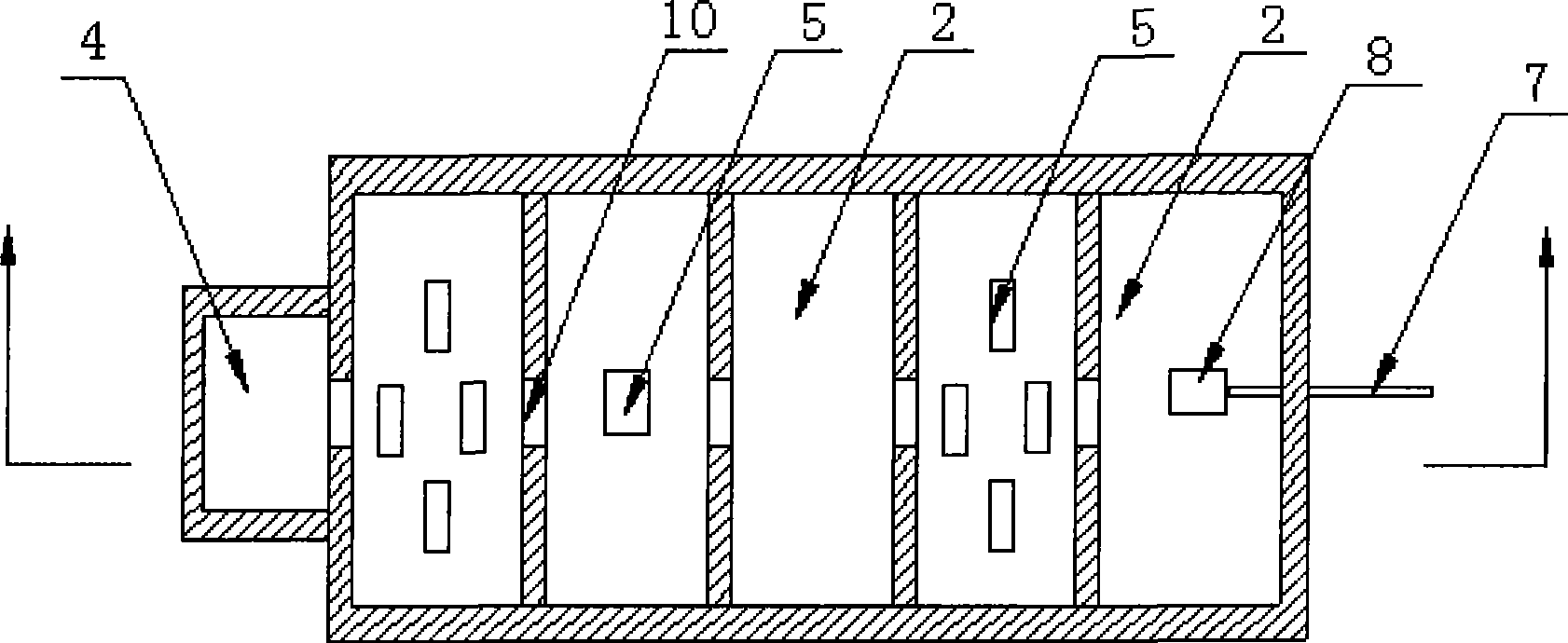
[0035] Such as image 3 , Figure 4 and Figure 5 As shown, the difference between Embodiment 2 and Embodiment 1 lies in the input-output structure. In Embodiment 2, the input-output structure is composed of a coaxial probe 7 and a coupling column 8. One end of the coupling column 8 is vertically connected to the partition plate 3, and the other end is suspended in the air. , the coaxial probe 7 passes through the side wall of the resonant cavity 2 and connects with the coupling column 8 .

[0036] In the present invention, by folding the waveguide filter in the prior art, the original structure in which the resonant cavity is located on the same plane becomes a three-dimensional structure arranged above and below the resonant cavity, thereby saving the plane space occupied by the waveguide filter and saving waveguide filtering. The material of the filter greatly facilitates the integration of the waveguide filter and the external circuit.


PUM


Abstract

The invention discloses a folded waveguide filter, which consists of a filter upper main body, a filter lower main body, a clapboard and a connection structure, wherein the filter upper main body is arranged above the filter lower main body, and the clapboard is arranged between the filter upper main body and the filter lower main body; and the connection structure is arranged at the same end of the filter upper main body and the filter lower main body to connect the filter upper main body and the filter lower main body into a whole so that a microwave signal passage is formed among the filter upper main body, the connection structure and the filter lower main body. The folded waveguide filter not only reduces the plane space occupied by a resonant cavity manifold and facilitates the integration of the waveguide filter and an external circuit, but also achieves the cross coupling between the filter upper main body and the filter lower main body so that the waveguide filter has better band external inhibition.

Description

technical field [0001] The present invention relates to a waveguide filter, in particular to a folded waveguide filter. Background technique [0002] The currently known waveguide filters all achieve cavity coupling on a single plane, that is, a single-layer waveguide filter. All resonators of this filter are on the same plane. Many, when the cavity of a single resonant cavity is large, it will occupy a large plane space. Therefore, this structure in the prior art not only increases the planar occupied space of the filter, but also causes inconvenience to the integration of the circuit system. Contents of the invention [0003] The purpose of the present invention is to provide a folded waveguide filter, which not only doubles the plane space occupied by the filter, saves filter manufacturing materials, increases design flexibility, but also enables the present invention to have better out-of-band suppression, which is convenient for use with External circuit integration...

Claims


Application Information

Patent Timeline
Patent Type & Authority Applications(China)
IPC IPC(8): H01P1/208
Inventor 王清源王玺
Owner 鄄城旭阳实业有限公司
Learn More