
Magnetoelectric sensor adjusting circuit

A magnetoelectric sensor, magnetoelectric sensor technology, applied in the direction of instruments, electrical control, machines/engines, etc., can solve the problems of economic loss, inability to pre-determine, complicated replacement process, etc., to save maintenance costs and reduce fault diagnosis time. Effect

Inactive Publication Date: 2009-09-02
NO 70 INST OF CHINA NORTH IND GRP
View PDF0 Cites 33 Cited by
  • Summary
  • Abstract
  • Description
  • Claims
  • Application Information

AI Technical Summary

Problems solved by technology

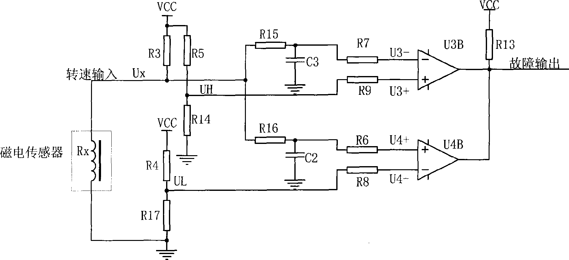
[0002] The magnetoelectric speed sensor is a key component in engine control. The commonly used conditioning circuit is to filter and shape the positive harmonic signal output by the sensor to form a rectangular wave signal, which is used for pulse collection by the single-chip microcomputer system. The fault judgment of the sensor can only be Whether the signal output of the sensor is completed by "open circuit", "short circuit" or relying on the sensor when the gear rotates, it cannot be judged whether it is good or bad in advance, so it is impossible to accurately judge the quality of the magnetoelectric speed sensor before the engine can reach the operating condition , wait until the relevant components are assembled and the engine is put on the bench, if the sensor is found to be damaged, the replacement process will be more complicated, resulting in unnecessary economic losses

Method used


Image

  • Magnetoelectric sensor adjusting circuit
  • Magnetoelectric sensor adjusting circuit
  • Magnetoelectric sensor adjusting circuit

Examples


Embodiment Construction

[0012] The preferred embodiments of the present invention will be further described below in conjunction with the accompanying drawings.

[0013] A magnetoelectric sensor conditioning circuit includes a signal conditioning circuit and a fault diagnosis circuit, both of which use the output of the magnetoelectric sensor as their input.

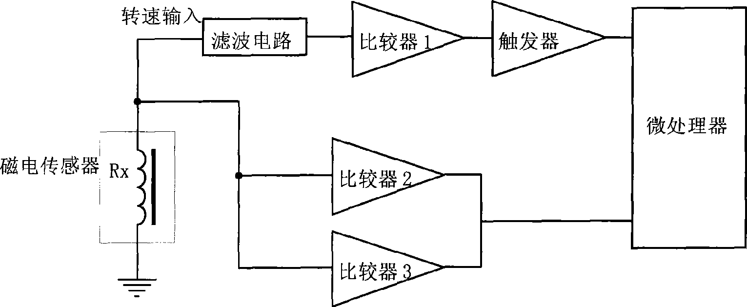
[0014] like image 3 As shown, the output signal of the magnetoelectric sensor enters the comparator 1 through the filtered current, and the rectangular wave signal is output by comparison, and the trigger performs hysteresis comparison processing on the signal, and then the microprocessor calculates the speed. At the same time, Rx is the equivalent resistance of the magnetoelectric sensor coil. When the magnetoelectric sensor coil has no signal, the voltage division signal on the internal resistance Rx of the sensor is compared with the upper limit voltage by comparator 2, and the lower limit voltage is compared by comparator 3. When When the ...


PUM


Abstract

The invention belongs to the technical field of engine electronic control, in particular to a magnetoelectric sensor adjusting circuit which comprises a signal adjusting circuit and a failure diagnostic circuit which both use the output of the magnetoelectric sensor as the input; the magnetoelectric sensor outputs signals, the signals to enter into a comparer 1 through filter current and the comparer outputs square signals through comparison; and the square signals are delayed and compared by a trigger and then are carried out the rotation calculation by a microprocessor. The magnetoelectric sensor adjusting circuit can judge whether the inner resistance of the sensor is within the reasonable range on the basis of the completion of open circuit and short circuit, detect the fault of the sensor in advance, effectively reduce the fault detection time, save the maintenance cost and effectively process the positive harmonic signals output by the sensor when the amplitude of the output signals of the sensor is 2V to 100V and the frequency is within the wide range of 50 Hz to 5 KHz.

Description

technical field [0001] The invention belongs to the technical field of engine electronic control, and in particular relates to a magnetoelectric sensor conditioning circuit. Background technique [0002] The magnetoelectric speed sensor is a key component in engine control. The commonly used conditioning circuit is to filter and shape the positive harmonic signal output by the sensor to form a rectangular wave signal, which is used for pulse collection by the single-chip microcomputer system. The fault judgment of the sensor can only be Whether the signal output of the sensor is completed by "open circuit", "short circuit" or relying on the sensor when the gear rotates, it cannot be judged whether it is good or bad in advance, so it is impossible to accurately judge the quality of the magnetoelectric speed sensor before the engine can reach the operating condition , After the relevant components are assembled and the engine is put on the stand, if the sensor is found to be d...

Claims


Application Information

Patent Timeline
Patent Type & Authority Applications(China)
IPC IPC(8): G01P21/00F02D41/00
Inventor 白思春褚全红孟长江王孝贾利姜承赋杨凤秋孟庆涛
Owner NO 70 INST OF CHINA NORTH IND GRP
Learn More