Fixed constant velocity universal joint

A constant velocity universal joint, fixed technology, applied in the direction of elastic couplings, mechanical equipment, couplings, etc., to achieve the effect of improving rigidity, preventing deformation and preventing wear

Active Publication Date: 2012-11-21
NTN CORP
View PDF1 Cites 0 Cited by
  • Summary
  • Abstract
  • Description
  • Claims
  • Application Information

AI Technical Summary

Problems solved by technology

Therefore, in this case, problems such as a decrease in load capacity at high angles and an increase in contact surface pressure between the inner ring and the inner spherical surface of the cage cannot be prevented.

Method used


Image

  • Fixed constant velocity universal joint
  • Fixed constant velocity universal joint
  • Fixed constant velocity universal joint

Examples


Embodiment Construction

[0085] Below, based on Figure 1 to Figure 19 Basic embodiments of the present invention will be described. After that, based on Figure 20 to Figure 28 , Figure 29 to Figure 30 as well as Figure 31 to Figure 40 Three modified embodiments will be described.

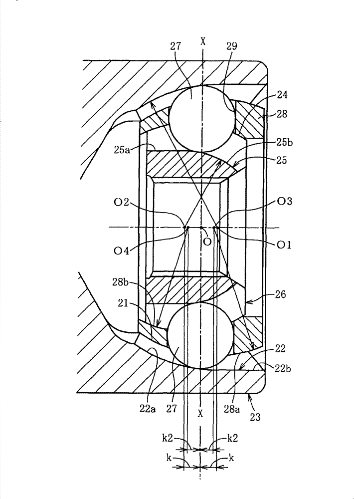
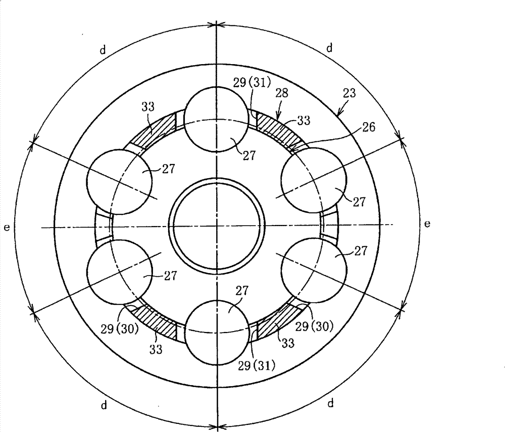
[0086] like figure 1 As shown, the fixed-type constant velocity universal joint according to the basic embodiment includes: an outer ring 23 as an outer member on which a plurality of track grooves 22 are formed in the axial direction at unequal intervals in the circumferential direction on the inner spherical surface 21; The spherical surface 24 is formed with a plurality of track grooves 25 paired with the track grooves 22 of the outer ring 23 in the axial direction at unequal intervals in the circumferential direction. The outer ring 26 is an inner member; A plurality of balls 27 for transmitting torque between the track grooves 25 of the inner ring 26 ; a cage 28 for holding the balls 27 between the inner sphe...


PUM


Abstract

The present invention provides a fixed constant velocity universal joint reduced in size, having no reduction in load capacity despite of the reduction in the size and even if the joint is operated at a large operation angle, and having improved high-angle strength and durability achieved by allowing running of balls on to a track under high angle operation. In the fixed constant velocity universal joint, the pockets (29) of a cage (28) are composed of four pockets that are a pair of long pockets (30) having a large circumferential spacing and a pair of short pockets (31) having a small circumferential spacing. The pair of long pockets (30) is displaced 180 degrees away from each other in the circumferential direction, and the pair of short pockets (31) is displaced 180 degrees away from each other in the circumferential direction. As a result, the long pockets (30) and short pockets (31) are alternately arranged in the circumferential direction. Each long pocket (30) receives two balls (27), and each short pocket (31) receives one ball (27). Projections (36) projecting inward of each long pocket are arranged at opposed long sides of the long pocket (30). Two ball-receiving sections (38) arranged side by side with a slit (37) in between are formed in each long pocket (30).

Description

technical field [0001] The present invention relates to a fixed constant velocity universal joint. The fixed constant velocity universal joint is used in the power transmission system of automobiles and various industrial machinery, and allows angular displacement between the two shafts on the driving side and the driven side. Background technique [0002] For example, a fixed type constant velocity universal joint is one of constant velocity universal joints used as means for transmitting rotational force from an engine of an automobile to a wheel at a constant velocity. This fixed type constant velocity universal joint has a structure that connects two shafts on the driving side and the driven side, and can transmit rotational torque at a constant velocity even when the two shafts have an operating angle. In general, as the above-mentioned fixed type constant velocity universal joint, a ball cage type (BJ) and an under cut free type (UJ) are widely known. [0003] For ex...

Claims


Application Information

Patent Timeline
Patent Type & Authority Patents(China)
IPC IPC(8): F16D3/224F16D3/223F16D3/2237F16D3/2245
Inventor 藤尾辉明星野学中川亮菅沼和三郎
Owner NTN CORP
Why Eureka
Try Eureka