An electron column using a magnetic lens layer

A technology of electron column and magnetic lens, applied in nanotechnology, circuit, discharge tube and other directions for information processing, can solve the problem of difficult to precisely control the lens, and achieve the effect of reducing voltage, precise focusing, and easy deflection.

Inactive Publication Date: 2009-08-19
CEBT
View PDF0 Cites 0 Cited by
  • Summary
  • Abstract
  • Description
  • Claims
  • Application Information

AI Technical Summary

Problems solved by technology

Therefore, it may not be preferable to apply high voltages, and it may be difficult to precisely control the lens when high voltages are used

Method used


Image

  • An electron column using a magnetic lens layer
  • An electron column using a magnetic lens layer
  • An electron column using a magnetic lens layer

Examples


Embodiment Construction

[0023] With reference to the following figures, various embodiments of the present invention will be described. At this point, it should be noted that various embodiments are used to illustrate the present invention so that those skilled in the art can easily understand the present invention, but are not intended to limit the rights of the present invention.

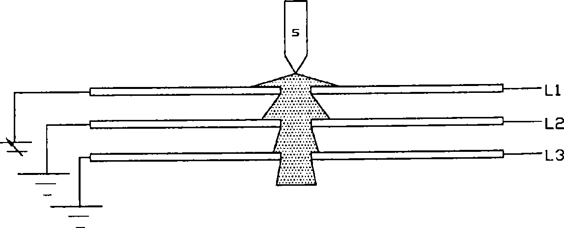
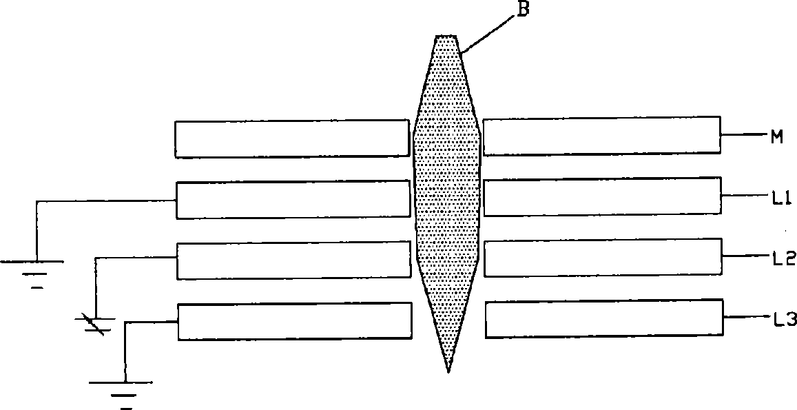
[0024] image 3 It is a cross-sectional view conceptually showing a section of a lens layer for focusing according to the present invention. Figure 4 To illustrate a cross-sectional view of an embodiment in which an electrode layer using a permanent magnet according to the present invention is used in a source lens. Figure 5 is a top view of a magnetic lens layer according to the present invention. Image 6 It is a top view of the electrode layer of a general electrostatic lens.

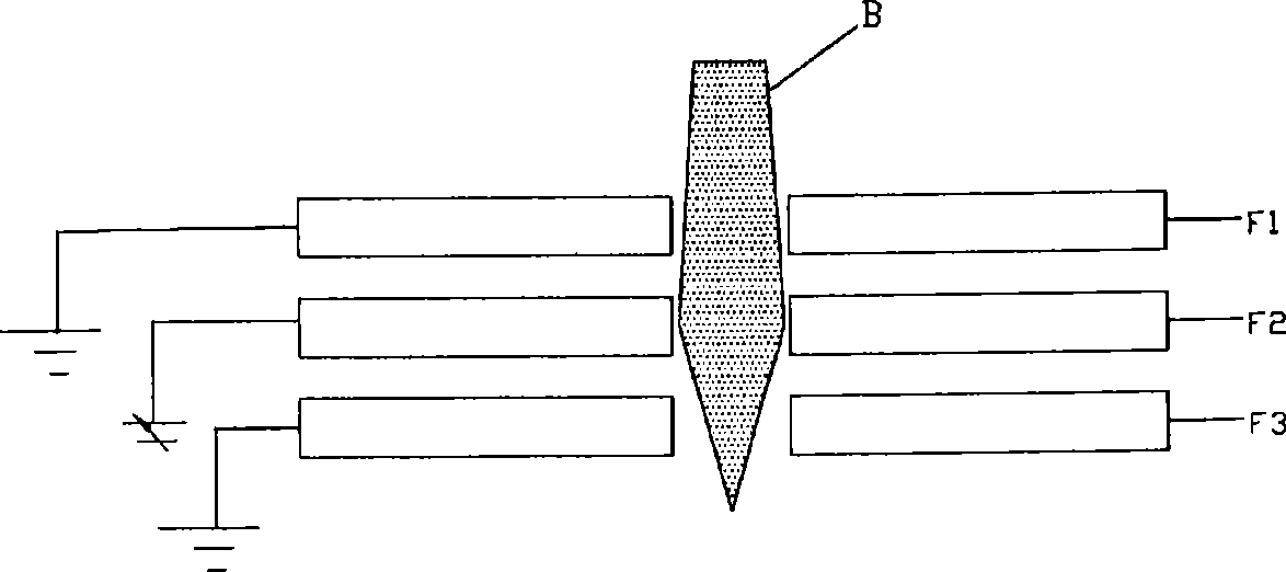
[0025] exist image 3 In , the uppermost electrode layer L1 and the lowermost electrode layer L3 are grounded, and the intermediate elec...


PUM


Abstract

Disclosed herein is an electron column using a magnetic lens layer. The electron column includes a magnetic lens layer for condensing an electron beam using permanent magnets. The magnetic lens layer includes a support plate, an aperture formed through the support plate, and permanent magnets arranged around the aperture and disposed on or inserted into the support plate.

Description

technical field [0001] The present invention generally relates to a lens assembly for an electron column, and more particularly, to a lens assembly and a focusing method in which a permanent magnet is used in an electron column to prefocus an electron beam passing through a magnetic lens layer, and then to precisely focus the electron beam, This facilitates focusing and control of the electron beam. Background technique [0002] Generally, electron columns include microelectronic columns, each microelectronic column includes an electron emission source for emitting electrons, a source lens for forming an effective electron beam, a deflector for deflecting the electron beam, and a focusing lens for focusing the electron beam. lens. The electron column performs focusing using a source lens if necessary. Therefore, focusing is performed using a dedicated focusing lens (for example, a single lens) or a source lens. [0003] This focusing is performed using a lens comprising t...

Claims


Application Information

Patent Timeline
Patent Type & Authority Applications(China)
IPC IPC(8): H01J37/14
CPCB82Y10/00H01J37/3174H01J2237/1205H01J2237/1405H01J2237/3175H01J37/12H01J37/143H01J37/145H01J2237/26B82Y40/00H01J37/14
Inventor 金浩燮
Owner CEBT
Why Eureka
Try Eureka