
Multi cutter-head extruder and assembling method thereof

An assembly method and extruder technology, which is applied in the field of tandem disc extruder and its assembly, can solve the problems of limited interchangeability, inconvenience, and large friction coefficient, and achieve easy disassembly, convenient adjustment, and improved dispersion Effect

Inactive Publication Date: 2009-08-19
成都宇洋高科技发展有限责任公司
View PDF1 Cites 4 Cited by
  • Summary
  • Abstract
  • Description
  • Claims
  • Application Information

AI Technical Summary

Problems solved by technology

This patent avoids some outstanding problems in the previous tandem grinding disc extruder, improves the shearing performance, and mainly solves the disadvantages of the past that the moving disc cannot push the material forward and the resistance is too large.
However, there are still defects in this patent, the inner bushing and the static disc form an axial fixation with the machine barrel through a rectangular square key
When disassembling, it is very inconvenient due to the large friction coefficient, and once one of the square keys is slightly twisted, the whole screw will be stuck and cannot be taken out
In addition, from a structural point of view, although the gap between the disk surfaces can be adjusted, the gap is relatively large, usually 1-1.5 mm, in order to improve the shearing, compressibility and dispersion.
In addition, due to the limitation of the current assembly method, its interchangeability is also limited, and it is very troublesome to adjust the position of the cutter head group

Method used


Image

  • Multi cutter-head extruder and assembling method thereof
  • Multi cutter-head extruder and assembling method thereof
  • Multi cutter-head extruder and assembling method thereof

Examples


Embodiment 1

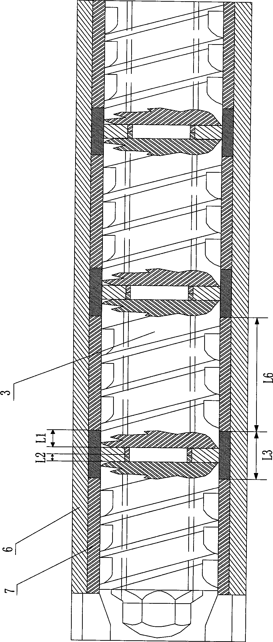
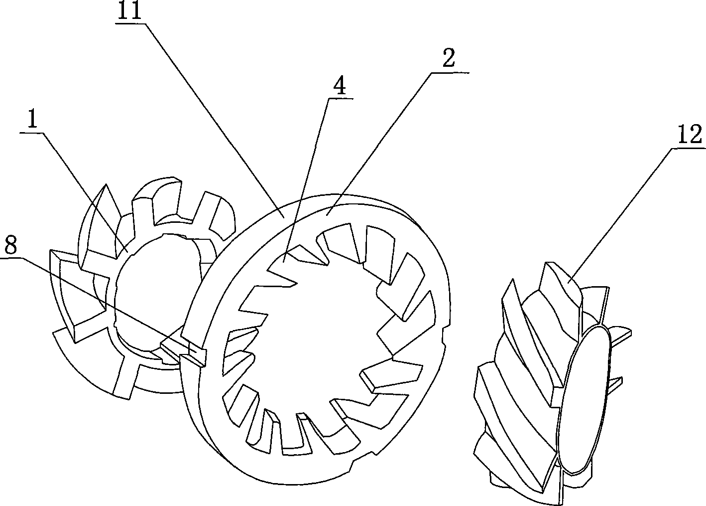
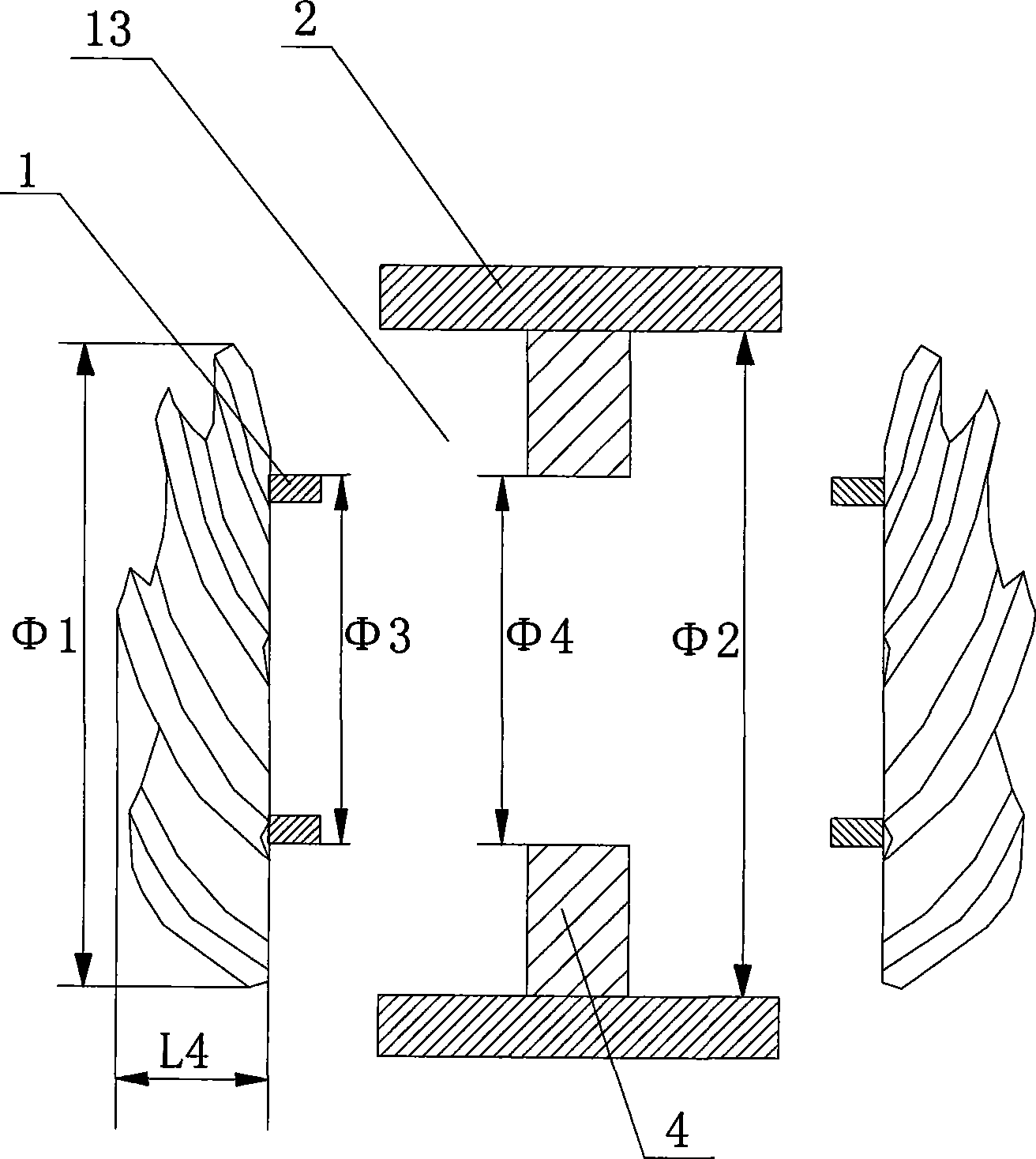
[0024] Embodiment 1, when installing the fitted cutterhead, first determine the total length L of the fitted cutterhead 3 =96mm, and the length of the groove on the static cutter head 11 is 15mm, and the extension length L of the boss 2 to both sides 1 = 40.5 mm. Axial length L of the movable cutterhead 12 4 is 40mm, the length L of the extension part of boss 1 2 = 8mm. Then make the axial length L of the inner bushing 7 6 =192mm, conveying thread module 3 length L 5 =48mm. Therefore, it is determined that the disc occlusal gap between the dynamic disc and the static disc is 0.5mm.

Embodiment 2

[0025] Embodiment 2, when installing the fitted cutterhead, firstly the total length L of the fitted cutterhead 3 =96mm, the length of the groove on the static cutter head 11 is 15mm, and the extension length L of the boss 2 to both sides 1 = 40.5 mm. Axial length L of the movable cutterhead 12 4 It is 40.3mm, and the length L of the extension part of the boss 12 = 7.7 mm. Then make the axial length L of the inner bushing 7 6 =96mm, delivery thread module 3 length L 5 =48mm. Therefore, it is determined that the interlocking gap between the dynamic and static discs is 0.2mm.

[0026] From the above two embodiments, we can see that adjusting the axial length of the movable cutter head 12 and the length of the extension of the boss 1 can adjust the occlusal gap between the disk surfaces, so that the disk surface gap can reach high precision and further improve the shear performance. A new method is adopted in the assembly process, so when the combined cutter head is replace...


PUM

PropertyMeasurementUnit
lengthaaaaaaaaaa
lengthaaaaaaaaaa
lengthaaaaaaaaaa

Abstract

The invention discloses a multi-cutter extruder, which comprises a machine barrel, wherein the inside of the machine barrel is provided with an inner bushing, a screw and a closing type cutter; the closing type cutter consists of a dynamic cutter and a static cutter; the static cutter is connected with the inner bushing into a whole; and the dynamic cutter is jointed with a conveying threaded module. The improvement on the closing type cutter structure, an adopted new assembly method and the fixation of the inner bushing, the static cutter and the machine barrel with ballistic scrolling keys facilitate the adjustment of the position of the closing type cutter during actual use, so the extruder meets more actual production requirements. The high-precision cutter panel occlusal clearance ensures the elements obtain precise occlusal clearance in the screw, greatly improves the shearing performance, compressibility and dispersibility, and facilitates the detachment and installation of the screw.

Description

technical field [0001] The invention relates to a multi-cutter disc extruder and an assembly method thereof, in particular to a series grinding disc extruder comprising a multi-head spiral movable disc extruder and an assembly method thereof. Background technique [0002] The existing tandem disc extruder adopts a combined or semi-combined structure. , and strong dispersion. The characteristics are mainly reflected in the grinding disc work area. like Figure 4 As shown, the structure of the grinding disc is that both the moving and fixed discs have grooves. The two discs form a concave-convex surface, the fixed disc does not move, and the moving disc rotates. During the mixing process, the material passes through the concave-convex surfaces of the two discs to form a vortex, and is repeatedly sheared, compressed and replaced. It enters the extrusion section under the action of normal stress, and then extrudes from the die. The blended polymers passed through the tandem ...

Claims


Application Information

Patent Timeline
Patent Type & Authority Applications(China)
IPC IPC(8): B29C47/64B29C48/67B29C48/52
CPCB29C48/362B29C48/363B29C48/52
Inventor 叶小川
Owner 成都宇洋高科技发展有限责任公司
Learn More