
Automobile cornering illuminating apparatus and control method

A lighting device and control method technology, applied in signal devices, vehicle parts, transportation and packaging, etc., can solve the problems of high cost, large headlight movement space, complex structure, etc., and achieve the effect of cost reduction and improvement of lighting effect

Inactive Publication Date: 2009-08-12
郭廷麟 +1
View PDF0 Cites 9 Cited by
  • Summary
  • Abstract
  • Description
  • Claims
  • Application Information

AI Technical Summary

Problems solved by technology

[0006] This method requires a large headlight movement space, and the horizontal rotation is ±20°. This kind of structure is complex and costly, and it is not easy to accept for low-end and mid-range cars.

Method used


Image

  • Automobile cornering illuminating apparatus and control method
  • Automobile cornering illuminating apparatus and control method
  • Automobile cornering illuminating apparatus and control method

Examples


Embodiment 1

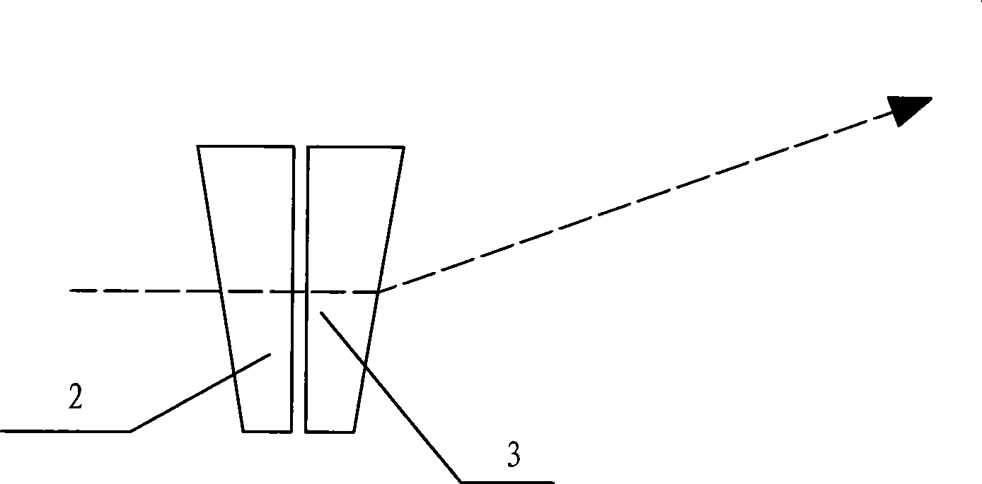
[0026] Such as figure 1 The car curve lighting device of the present invention shown includes a light source 1, and a first wedge mirror 2 and a second wedge mirror 3 are sequentially arranged in front of the light source 1, and the driving wheels include a first driving wheel 6 and a second driving wheel 7; The driving wheel comprises a first driven wheel 4 and a second driven wheel 5, the first wedge mirror 2 is arranged in the first driven wheel 4, the second wedge mirror 3 is arranged in the second driven wheel 5, the first driven wheel 4 and the first driven wheel The driving wheel 6 is meshed, the first driving wheel 6 is driven by the motor 8, and the motor 8 is controlled by the controller 10; the first driving wheel 6 is meshed with the passing wheel 9, and the first driving wheel 6 is arranged on the first driven wheel 4 and the passing wheel 9 Between, the passing wheel 9 is coaxial with the second driving wheel 7, and the second driving wheel 7 is engaged with the ...

Embodiment 2

[0031] The two driving wheels in Embodiment 1 are respectively driven by two motors. In the initial position, the first wedge mirror 2 deflects the light downward, and the second wedge mirror 3 deflects the light upward, as Figure 5 The slopes of the wedge mirrors shown are split. When turning, the controller sends rotation signals to the two motors at the same time, and the two motors reverse in equal amounts, so that the thick ends of the two wedge-shaped mirrors move forward and turn to one side, thereby realizing the deflection of light. Others are with embodiment 1.

[0032] The working principle of the present invention: according to the refraction principle of the wedge mirror, two wedge mirrors are set in front of the light source, the wedge mirror is at the initial position, the refraction of the light by the two wedge mirrors cancels each other, the light is not deflected, and the light is emitted from the two wedge mirrors , so as not to affect the forward light. ...


PUM


Abstract

The invention relates to an illuminating apparatus and a control method thereof, in particular to an automobile bend road illuminating apparatus and a control method thereof, belonging to the field of automobile illumination. The automobile bend road illuminating apparatus comprises a light source, two wedge prisms which are sequentially arranged in front of the light source and respectively arranged in different driven gears, and driving gears that are meshed with the driven gears and driven by a motor. The invention has the advantages that under the condition that no energy consumption is increased, the illuminating apparatus utilizes the light source of the existing headlight and refraction of 'double-wedge prisms' without whole movement to realize the level steering of upper beam or lower beam of the light and keep light distribution in line with a standard requirement and constant, thus reducing the cost and improving the illuminating effect.

Description

technical field [0001] The invention relates to a lighting device and a control method, in particular to a car curve lighting device and a control method, belonging to the field of car lighting. Background technique [0002] In the past, there were two ways for cars to achieve curve lighting: [0003] The first type is an additional light source, adding a light bulb on the left and right of the headlights, which will light up when turning. [0004] This method will inevitably increase energy consumption, and the generated light distribution does not meet the standard requirements, which constitutes a safety hazard. [0005] The second kind, swing headlight, headlight is contained on the frame that can rotate around the vertical axis, drives with motor. [0006] This method requires a large headlight movement space, and the horizontal rotation is ±20°. This kind of structure is complex and costly, and it is not easy to accept for low-end and mid-range cars. Contents of th...

Claims


Application Information

Patent Timeline
IPC IPC(8): B60Q1/12B60Q1/132B60Q1/24
Inventor 郭廷麟刘德润
Owner 郭廷麟
Learn More