Lens retreat structure

A lens, lens barrel technology, used in installation, optics, instruments, etc.

Active Publication Date: 2009-07-29
ASIA OPTICAL CO INC
View PDF2 Cites 6 Cited by
  • Summary
  • Abstract
  • Description
  • Claims
  • Application Information

AI Technical Summary

Problems solved by technology

However, this back-off method also has the above-mentioned defects

Method used


Image

  • Lens retreat structure
  • Lens retreat structure
  • Lens retreat structure

Examples


Embodiment Construction

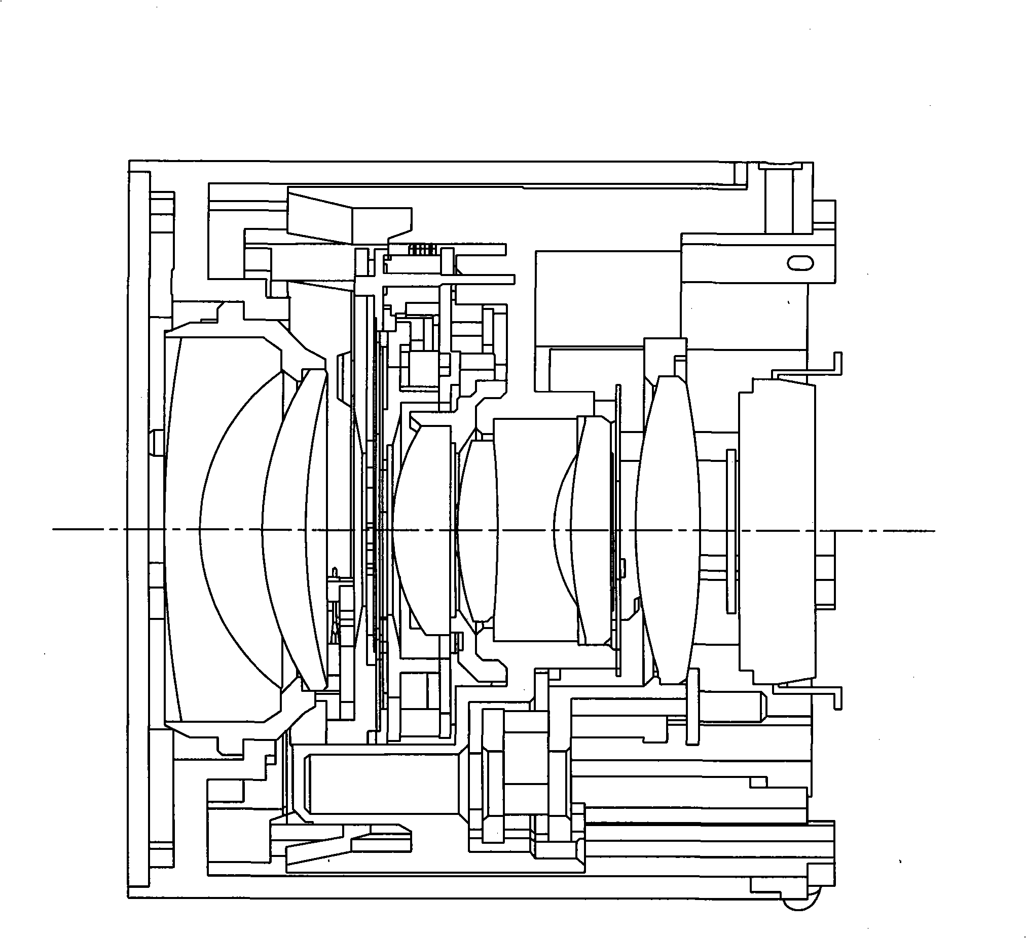
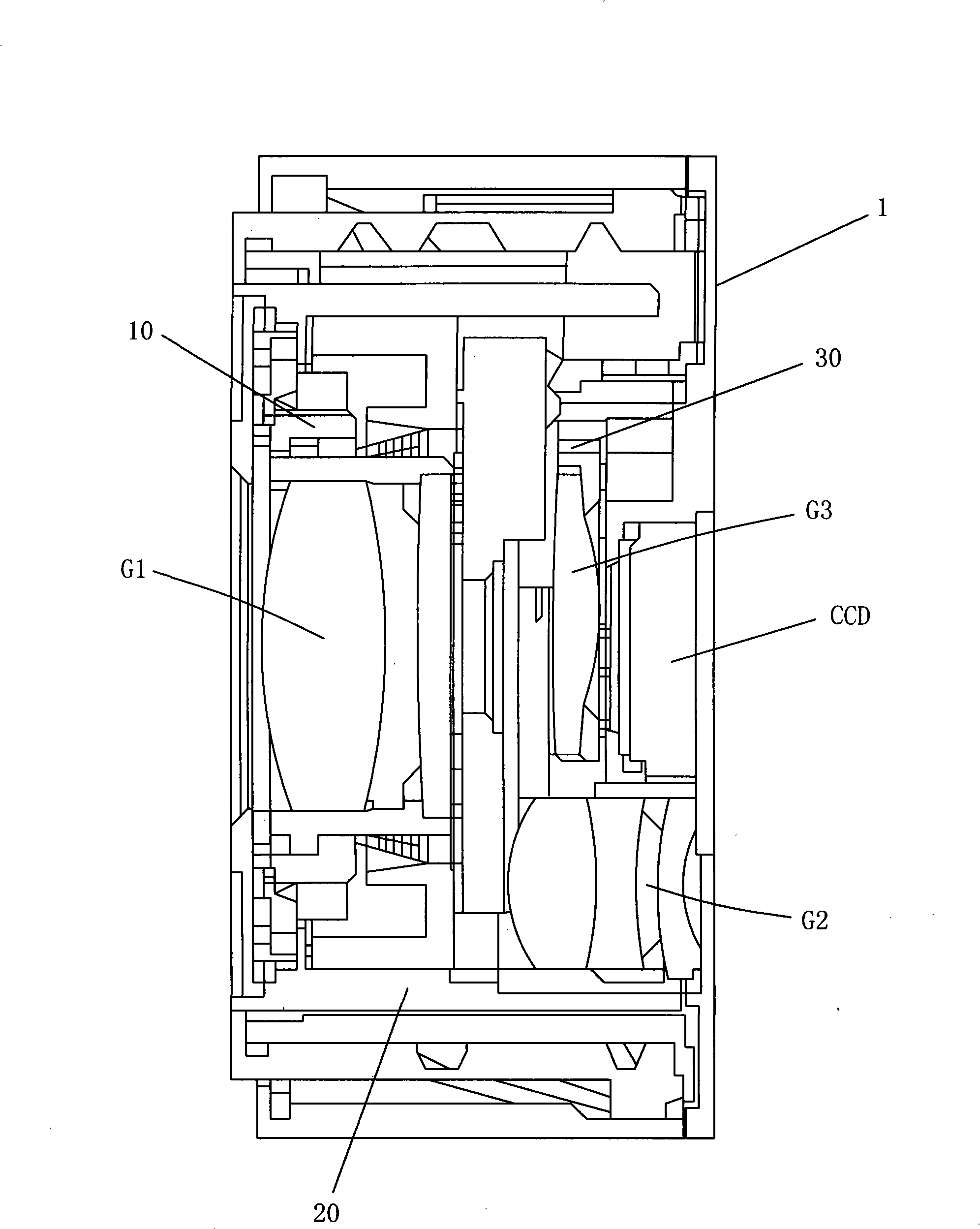
[0015] Please refer to figure 2 Shown is a schematic view of the state of the camera 1 of the present invention after the lens is retracted. The retractable lens system of the present invention includes a plurality of optical elements, such as the first lens group G1, the second lens group G2, the third lens group G3 and the sensor CCD, and the retractable lens system is shown in the figure when it is in a retracted state Schematic diagram, the camera 1 is in a non-working state at this time, and the second lens group G2 is slid out of the common optical axis, thereby reserving a receding space for other optical elements, and achieving the purpose of reducing the thickness of the camera in this way.

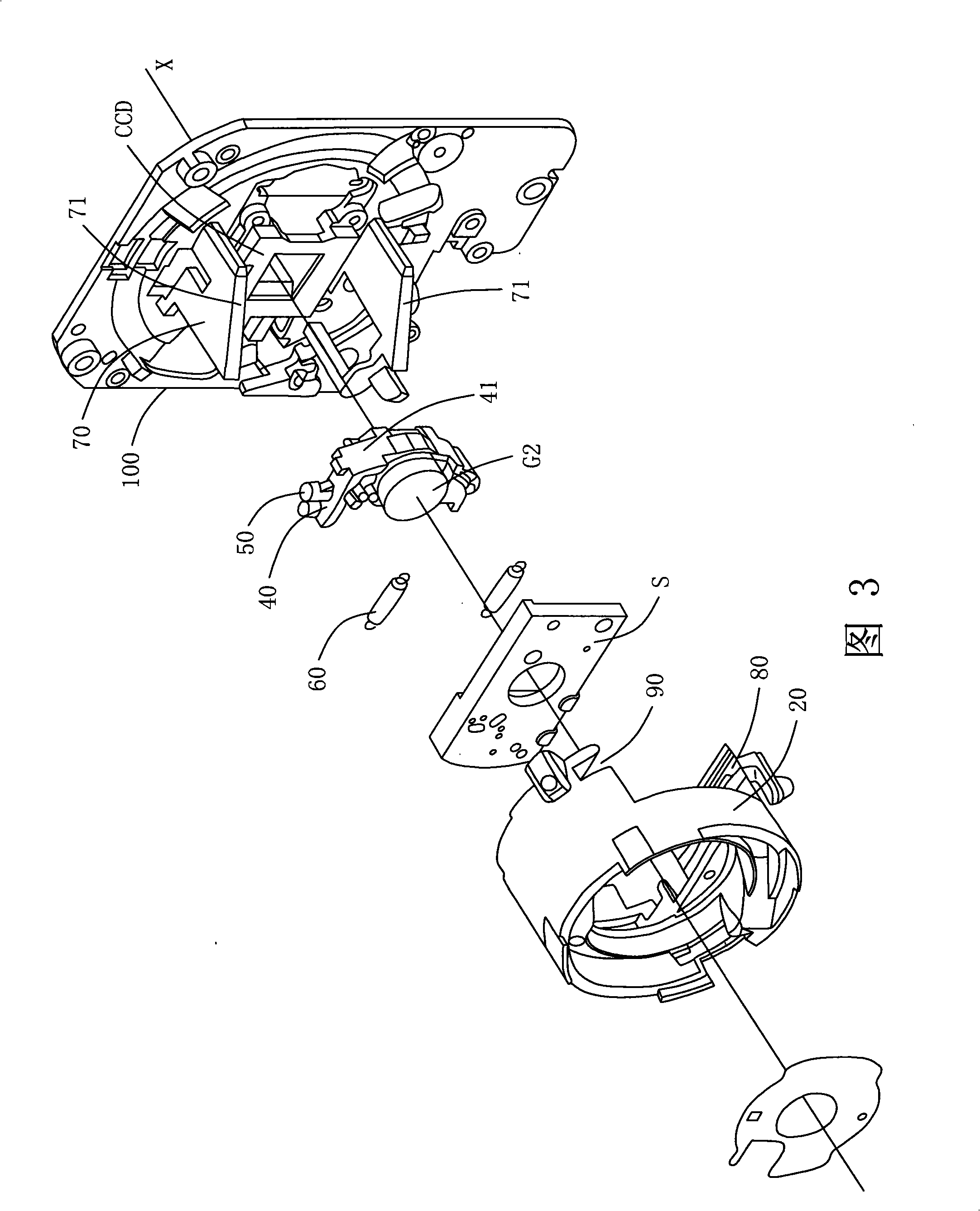
[0016] Please also refer to figure 2 And shown in Fig. 3, in the present embodiment, the camera 1 that adopts retractable lens system of the present invention has a fixed seat 100, in order to carry sensor CCD; The optical axis X moves to retract the lens; a shutter member S ...


PUM


Abstract

The invention discloses a lens withdrawal structure, comprising two sliding parts which are arranged on a lens group unit, two elastic parts by which the lens group unit can be connected with a drawtube, two sliding supporting parts which are arranged on a fixed base, and two track control parts which are arranged on one drawtube, wherein, the two sliding parts can slide stably along the inclined surface of the sliding supporting parts so as to drive the lens group unit to slide to the radial side of the common optical axis. The lens withdrawal structure is applied to a zoomer lens system which is provided with a plurality of lens group units; when the zoomer lens system is in use, the lens group units are arranged on the common optical axis; and when the zoomer lens system is not in use and requires to be withdrawn, one lens group unit slides to the radial side of the common optical axis by the lens withdrawal structure.

Description

【Technical field】 [0001] The present invention relates to a lens retracting structure, in particular to a lens retracting structure in a retractable lens system. When the retractable lens system is fully retracted, at least a part of the lens retracts to the outside the common optical axis of the system. 【Background technique】 [0002] The retractable lens can reduce the size of the camera in the non-shooting state, making the camera light and portable, but if figure 1 As shown in , after the retractable lens in existing cameras is retracted, its lens thickness cannot be smaller than the total thickness of all optical elements, so the camera body cannot be further reduced. [0003] At present, there are already many designs to make the fuselage thinner. Please refer to a retractable lens camera disclosed in Mainland China Patent Application No. 200510096681.7. The existing retractable lens camera is designed with a shift unit, which moves at least two lens groups out of th...

Claims


Application Information

Patent Timeline
Patent Type & Authority Applications(China)
IPC IPC(8): G02B7/02G02B7/04
Inventor 黄敦揆吴瑞德
Owner ASIA OPTICAL CO INC
Why Eureka
Try Eureka