
Honeycomb ceramic heat exchanger

A technology of honeycomb ceramics and heat exchangers, which is applied in the field of high-temperature and high-efficiency gas-gas honeycomb ceramic heat exchangers. Small size, convenient on-site construction, and improved safety

Inactive Publication Date: 2011-05-04
HEBEI UNIV OF TECH
View PDF4 Cites 0 Cited by
  • Summary
  • Abstract
  • Description
  • Claims
  • Application Information

AI Technical Summary

Problems solved by technology

There are mainly the following defects in this technology to be further solved: the frequent switching action of the four-way reversing valve is easy to be damaged, the life is short, and the operating cost is high; When it is large, it will affect the combustion stability and further affect the safety of the furnace
The existing ceramic heat exchanger improvement technology, such as Chinese patents CN85109173A, CN2295383Y, CN2096035U and CN2194497Y, etc., can save energy to a certain extent, but the air leakage rate of the heat exchanger needs to be further reduced

Method used


Image

  • Honeycomb ceramic heat exchanger
  • Honeycomb ceramic heat exchanger
  • Honeycomb ceramic heat exchanger

Examples


Embodiment 1

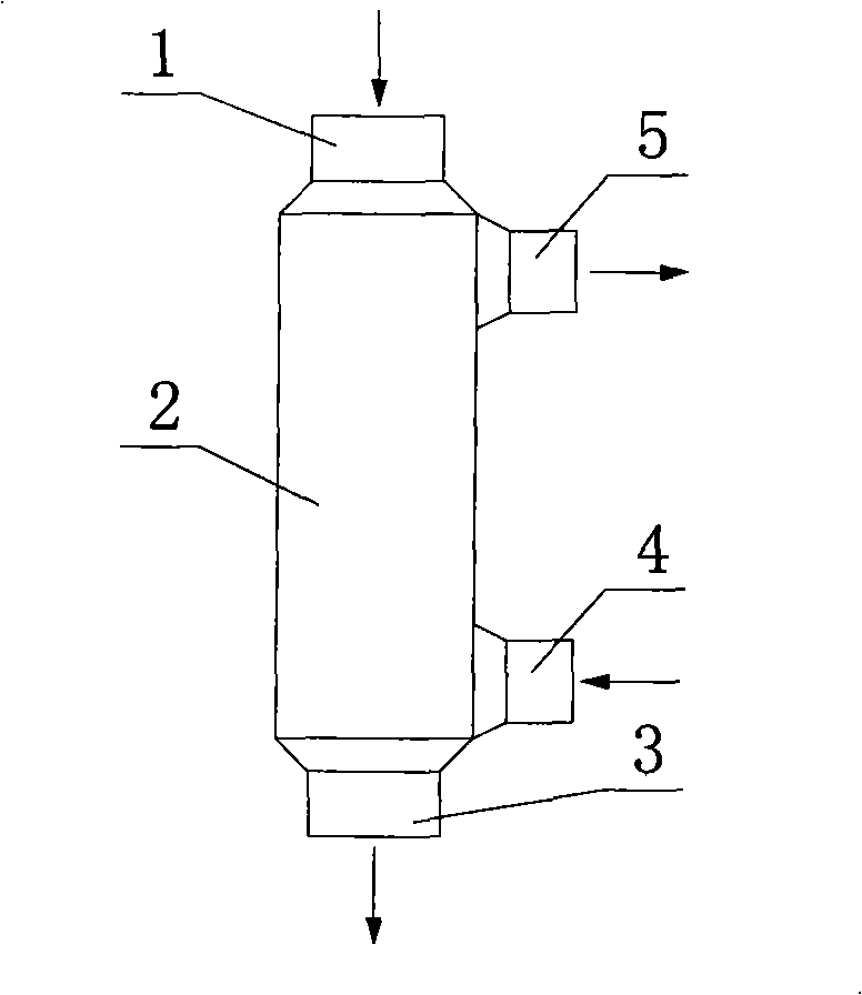
[0031] Honeycomb ceramic heat exchangers designed to heat only one gas (see Figure 12-13 ).

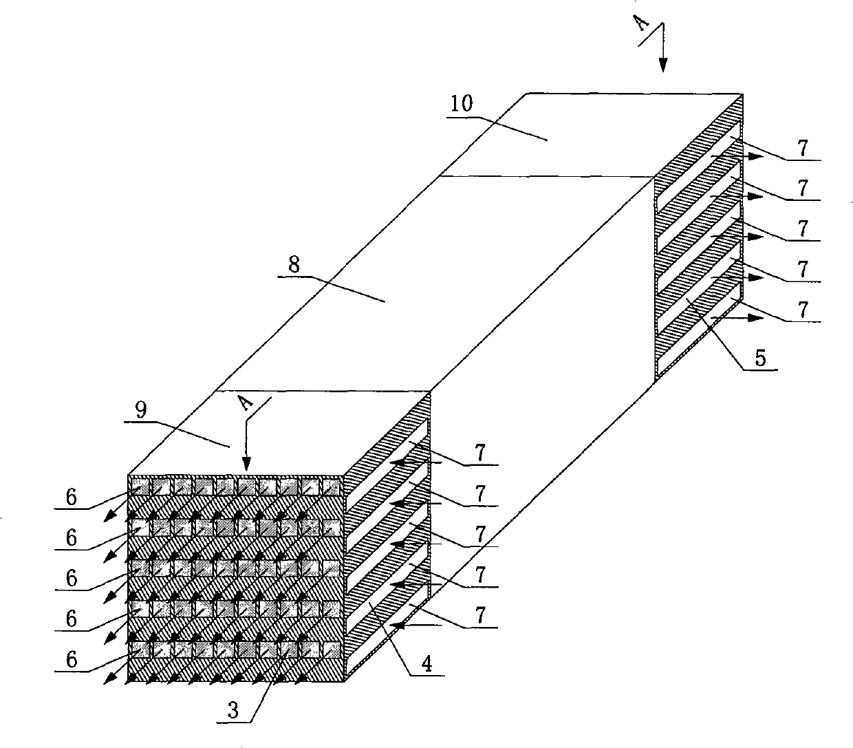
[0032] This heat exchanger is suitable for situations where it is not necessary to heat the fuel, but only the oxidant such as air or oxygen. The heat exchanger is mainly composed of flue gas inlet 1, flue gas outlet 3, air inlet 4, air outlet 5 and heat exchanger body 2; flue gas inlet 1 is installed at one end of heat exchanger body 2, and flue gas outlet 3 is installed At the other end of the heat exchanger main body 2; form a straight line connection; the air inlet 4 and the air outlet 5 are respectively installed at the two head basic units on the same side of the heat exchanger main body 2 to form a U-shaped connection (see Figure 12 ). Heat exchanger body 2 is the heart of the heat exchanger (see Figure 13 ), consisting of 4 main heat exchange body basic units 8, 2 A-type head basic units 9, 2 B-type head basic units 10 and 4 C-type head basic units 12. Among them, four ...

Embodiment 2

[0034] A honeycomb ceramic heat exchanger designed to heat two gases at the same time (one is air as the oxidant, and the other is blast furnace gas as fuel) (see Figure 14-15 ).

[0035] The heat exchanger is mainly composed of flue gas inlet 1, flue gas outlet 3, air inlet 13, air outlet 14, blast furnace gas inlet 15, blast furnace gas outlet 16 and heat exchanger main body 2. The main body 2 of the heat exchanger is the core of the heat exchanger, which consists of 9 main heat exchange body basic units 8, 3 A-type head basic units 9, 3 B-type head basic units 10 and 12 C-type heads The basic unit 12 is composed. Nine main heat exchange body basic units 8 are connected in parallel, and each head basic unit is connected in series with the main heat exchange body basic unit 8 according to the gas circulation process route. The main body of the heat exchanger 2 is divided into 3 layers, each layer includes 3 main heat exchange body basic units 8 and 6 required head basic un...


PUM


Abstract

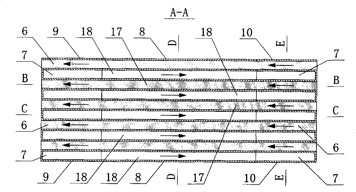
The invention relates to a honeycomb ceramics heat exchanger, comprising a smoke gas inlet, a heat exchanger body, a smoke gas outlet, a heated gas inlet and a heated gas outlet. The heat exchanger is characterized in that the heat exchanger body is formed by modular assembly of one or more than one main heat exchanging body basic unit and two end enclosure basic units or the end enclosure basic units numbered twice as much as the main heat exchanging body basic unit; the main heat exchanging body basic unit comprises a main heat exchanging body smoke gas channel and a main heat exchanging body heated gas channel; the main heat exchanging body smoke gas channel and the main heat exchanging body heated gas channel are in alternative tiering; flow directions of smoke gas in the main heat exchanging body smoke gas channel and the heated gas in the main heat exchanging body heated gas channel are opposite; the end enclosure basic unit comprises an end enclosure smoke gas channel and an end enclosure heated gas channel which are mutually perpendicular; the end enclosure smoke gas channel and the end enclosure heated gas channel are in alternative tiering; the shape and the structure ofthe end enclosure smoke gas channel and the end enclosure heated gas channel are the same as the shape and the structure of the main heat exchanging body smoke gas channel and the main heat exchanging body heated gas channel.

Description

technical field [0001] The invention belongs to the technology of industrial heat exchangers, in particular to a high-temperature and high-efficiency gas-gas honeycomb ceramic heat exchanger. Background technique [0002] High temperature air combustion technology is a new combustion technology developed in the 1990s. Through regenerative flue gas recovery, this technology can make the air preheating temperature reach 90% of the flue gas temperature, the furnace temperature uniformity is ≤±5°C, and its combustion thermal efficiency can reach 70% or even higher. This technology has many advantages such as high efficiency and energy saving, low pollution and environmental protection, good combustion stability, large combustion area, and wide fuel adaptability. The high-temperature air combustion technology uses the frequent switching of the four-way reversing valve to alternately pass the flue gas and the heated gas through the regenerator to realize the heat exchange between...

Claims


Application Information

Patent Timeline
Patent Type & Authority Patents(China)
IPC IPC(8): F28D20/00
CPCY02E60/14
Inventor 吴晋湘苟湘王恩宇刘联胜
Owner HEBEI UNIV OF TECH
Learn More