Multi-rotor wheel-leg type multifunctional air robot and sports programming method thereof
An aerial robot and robot technology, applied in the field of machinery, can solve the problems of limited application scope and single aerial robot, and achieve the effect of wide application scope, strong obstacle crossing ability, and easy realization.
Inactive Publication Date: 2011-01-05
BEIHANG UNIV
View PDF0 Cites 1 Cited by
- Summary
- Abstract
- Description
- Claims
- Application Information
AI Technical Summary
Problems solved by technology
In the field of research on aerial robots based on aircraft platforms, aerial robots are mostly limited to a single task, which limits their scope of application
Method used
View moreImage
Smart ImageViewing Examples
Examples
Embodiment Construction
Login to View More PUM
 Abstract
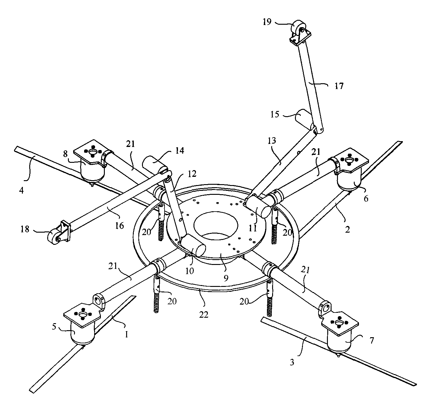
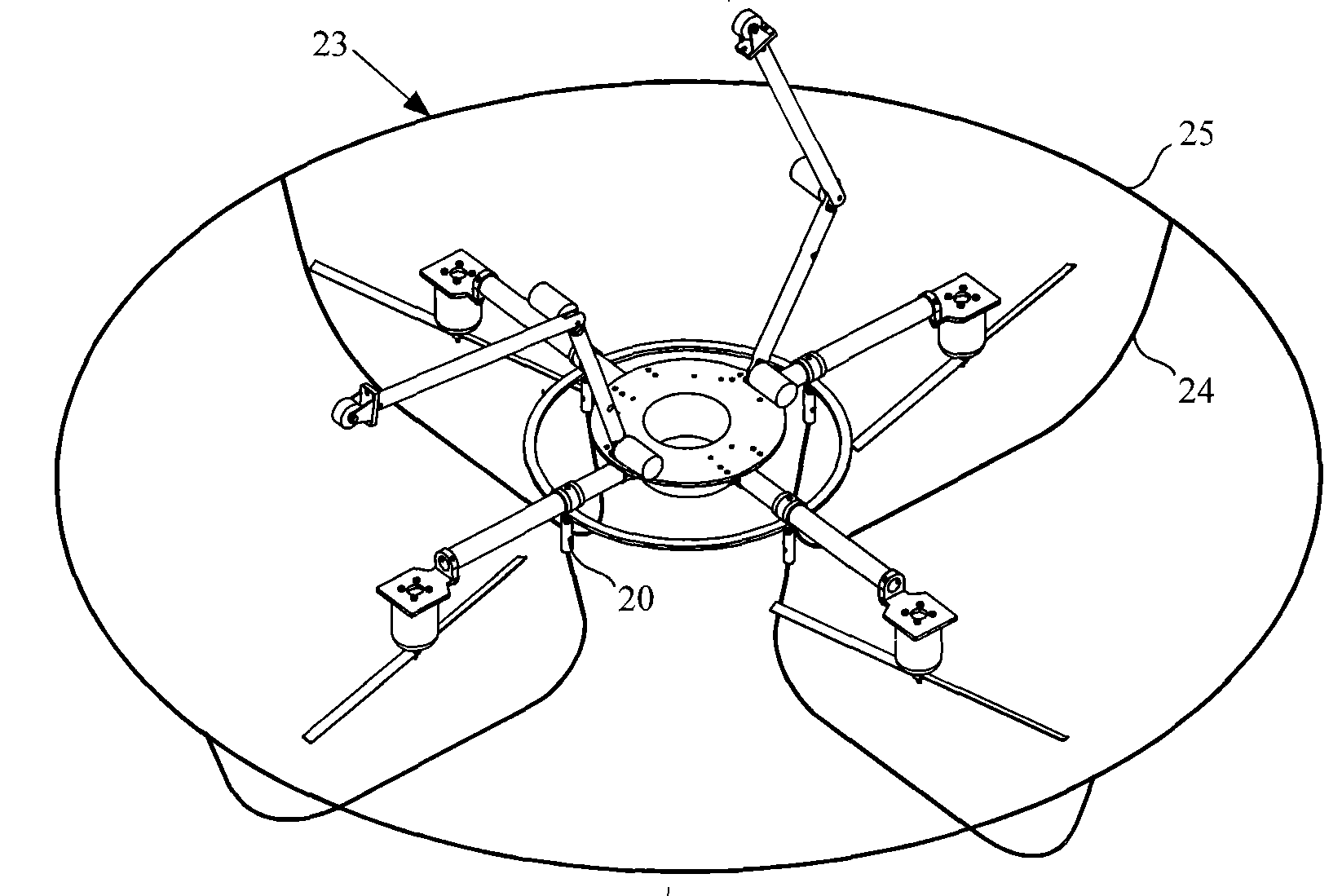
The invention discloses a multi-rotator leg-wheeled multifunctional aerial robot and a motion planning method thereof. The robot comprises rotators A, B, C and D, rotator driving motors A, B, C and D, wall-climbing thighs A and B, wall-climbing legs A and B, hip joint driving motors A and B, knee joint driving motors A and B, a robot main body, a wall-surface running wheels A and B, a ground supporting rod, rotating supporting rods and a rigidity-strengthened ring. The motion planning process comprises the motion planning of the robot in flight state, the motion planning of the robot undergoing a change from the flight state to a wall climbing state, the motion planning of the robot in a wall climbing state, the motion planning of the robot crossing an obstacle during wall climbing, and the motion planning of the robot undergoing a change from the wall climbing state to the flight state. The robot realizes the fusion of a rotator type aircraft and a leg-wheeled movement mechanism, is simple in mechanical structure and easy to realize, and has the advantages of high stability, small volume, strong adaptability to wall surfaces, large obstacle crossing capacity, wide application range and the like.
Description
A multi-rotor leg-wheeled multifunctional aerial robot and its motion planning method technical field The invention relates to an aerial robot, in particular to a multi-rotor leg-wheeled multifunctional aerial robot, belonging to the mechanical field. Background technique At present, many application fields require the aircraft to be able to fly at low altitude and low speed, perform low-altitude operations, and have good maneuverability and concealment. Therefore, there has been an aircraft system based on a single-rotor helicopter. This kind of single-rotor aircraft can realize low-altitude and low-speed flight, and can also complete certain low-altitude operations. However, due to the use of one rotor, the size of the rotor is generally relatively large, and it is more dangerous when working, and the control mechanism for the angle of attack of the single-rotor wing surface is complicated. , and it is a single point of failure, so the fault tolerance is poor. The mult...
Claims
Login to View More Application Information
Patent Timeline
 Patent Type & Authority Patents(China)
IPC IPC(8): B25J9/02B25J9/06B25J5/00B25J13/00
Inventor 丁希仑俞玉树米磊
Owner BEIHANG UNIV
Features
- R&D
- Intellectual Property
- Life Sciences
- Materials
- Tech Scout
- Unparalleled Data Quality
- Higher Quality Content
- 60% Fewer Hallucinations
Learn More Browse by: Latest US Patents, China's latest patents, Technical Efficacy Thesaurus, Application Domain, Technology Topic, Popular Technical Reports.
© 2025 PatSnap. All rights reserved.Legal|Privacy policy|Modern Slavery Act Transparency Statement|Sitemap|About US| Contact US: help@patsnap.com


