Packing case

A technology of packing boxes and beams, applied in the directions of packaging, transportation and packaging, loading/unloading, etc., can solve the problems of high work intensity, small buffer area, unfavorable on-site operation, etc. Effect

Inactive Publication Date: 2012-10-31
BEIJING AEONMED
View PDF0 Cites 0 Cited by
  • Summary
  • Abstract
  • Description
  • Claims
  • Application Information

AI Technical Summary

Problems solved by technology

[0003] Method 1, the packaging box with the equipment bottom beam as the force point, see the attached figure 1 , the packaging method is characterized by many points of stress and a wide range of forces, which is beneficial to ensure that the equipment will not be damaged due to vibration during transportation, but it requires multiple people to complete the packaging of the equipment, and the work intensity is high, which is very unfavorable for the site. operate
[0004] The second way is to use the equipment casters as the packing box, see the attached figure 2 The feature of this packaging method is that one person can complete the packaging work, but the casters as the stress point not only have relatively high requirements for the strength of the casters and the structure of the bottom beam, but also have a small buffer area, which affects the vibration resistance of the entire product. Also very demanding and therefore expensive packaging process
[0005] Neither method 1 nor method 2 can meet the requirements of efficiently completing the packaging work and maximizing the control of equipment costs.

Method used


Image

  • Packing case
  • Packing case
  • Packing case

Examples


Embodiment Construction

[0028] Exemplary embodiments of the present invention will be described below in conjunction with the accompanying drawings. In the drawings, the same components are denoted by the same reference numerals.

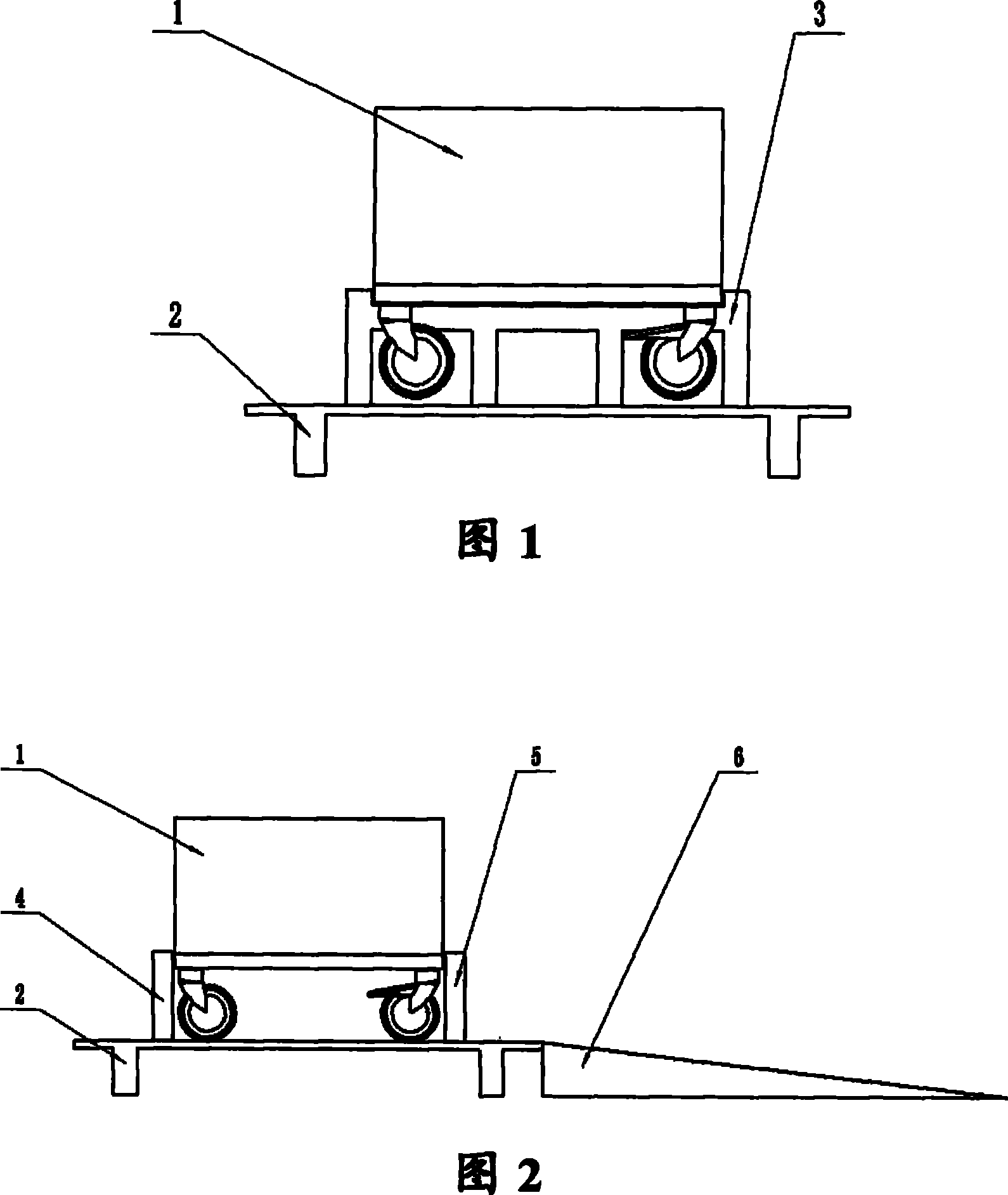
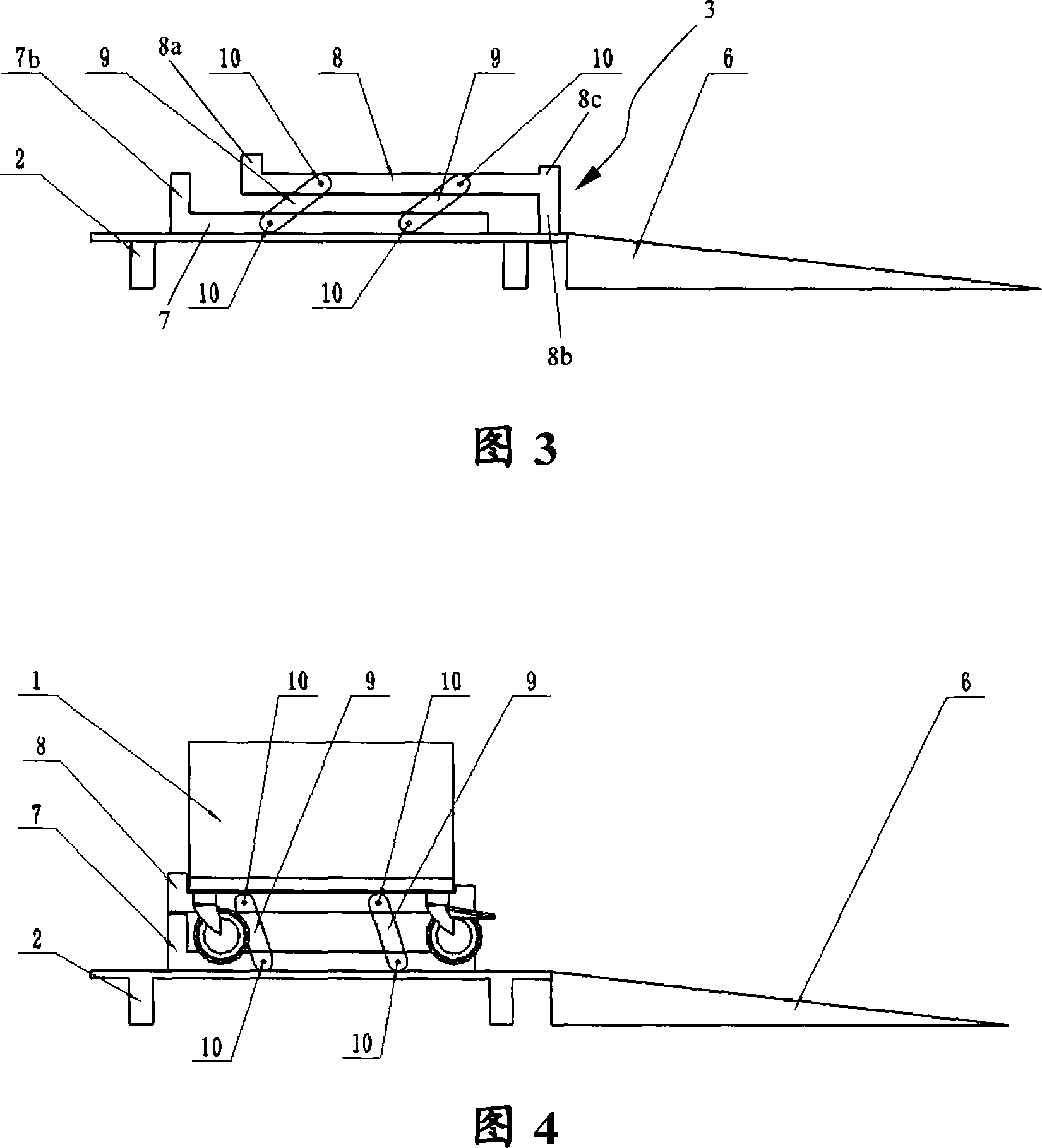
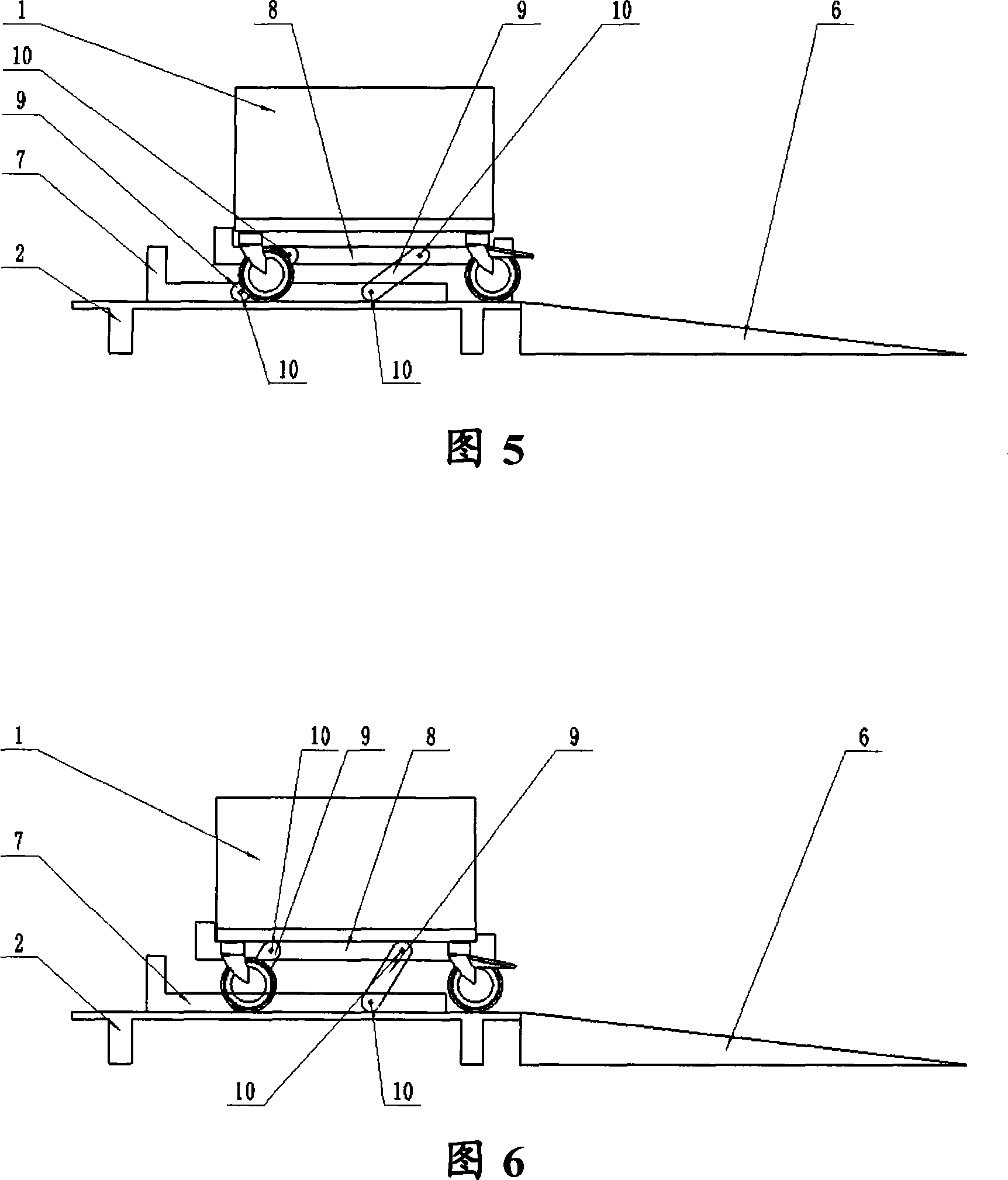
[0029] The structure of packing box of the present invention except box body is as image 3 As shown, it includes a packing box tray 2 and a cargo bottom support 3, which are arranged on the packing box tray 2; the cargo bottom support 3 includes: a first horizontal support portion, which is arranged in parallel with respect to the packing box tray 2; Rod 9, the two ends of the connecting rod are respectively pivotally connected with the packing box tray 2 and the first horizontal support part, and support the first horizontal support part from the first height to the second height, so The second height is higher than the first height. The first horizontal support portion of the cargo bottom bracket 3 can be fixed by a pair of symmetrical upper beams 8, and the second ho...


PUM


Abstract

The invention relates to a packaging box, which comprises a packaging box tray (2), a cargo base (3) and a connecting rod (9), wherein the cargo base (3) is arranged on the packaging box tray (2), comprises a first horizontal supporting part, and is arranged in parallel to the packaging box tray (2); both ends of the connecting rod (9) are pivotally connected with the packaging box tray (2) and the first horizontal supporting part respectively, so as to support the first horizontal supporting part from a first height to a second height; and the second height is higher than the first height.

Description

technical field [0001] The present invention relates to a packing box, which is especially suitable for packing equipment with casters. Background technique [0002] At present, there are two commonly used packaging methods for equipment with casters that need to be packaged: [0003] Method 1, the packaging box with the equipment bottom beam as the force point, see the attached figure 1 , the packaging method is characterized by many points of stress and a wide range of forces, which is beneficial to ensure that the equipment will not be damaged due to vibration during transportation, but it requires multiple people to complete the packaging of the equipment, and the work intensity is high, which is very unfavorable for the site. operate. [0004] The second way is to use the equipment casters as the packing box, see the attached figure 2 The feature of this packaging method is that one person can complete the packaging work, but the casters as the stress point not only...

Claims


Application Information

Patent Timeline
Patent Type & Authority Patents(China)
IPC IPC(8): B65D19/22B65D19/44B65G69/28
Inventor 易磊
Owner BEIJING AEONMED
Why Eureka
Try Eureka