
Method and equipment for digitized detection of double-plain shaft parallelism of optical instrument

An optical instrument and parallelism technology, applied in the direction of instruments, optical devices, measuring devices, etc., can solve the problems of large workload, long operation time, low detection and correction accuracy, etc., to reduce workload, improve accuracy, The effect of shortening the operation time

Inactive Publication Date: 2009-06-24
中国人民解放军92854部队军械修理厂
View PDF0 Cites 13 Cited by
  • Summary
  • Abstract
  • Description
  • Claims
  • Application Information

AI Technical Summary

Problems solved by technology

[0002] The existing manual detection method uses a double optical axis calibration instrument for detection. The detection method is: aim the instrument under test at the cross target, adjust the diopter screw to see the target clearly, move the optical axis instrument so that the left lens barrel is aligned with the cross target, Then check whether the cross targets on the right and left lens barrels are within the rectangular frame. If so, it indicates that the indicators meet the requirements. This method can only be a qualitative inspection
Since the detection method adopts manual operation, the input workload is large, the operation time is long, and the accuracy of detection and correction is low.

Method used


Image

  • Method and equipment for digitized detection of double-plain shaft parallelism of optical instrument
  • Method and equipment for digitized detection of double-plain shaft parallelism of optical instrument
  • Method and equipment for digitized detection of double-plain shaft parallelism of optical instrument

Examples


Embodiment Construction

[0022] like figure 1 As shown, a method for digitally detecting the parallelism of dual optical axes in an optical instrument comprises the following steps:

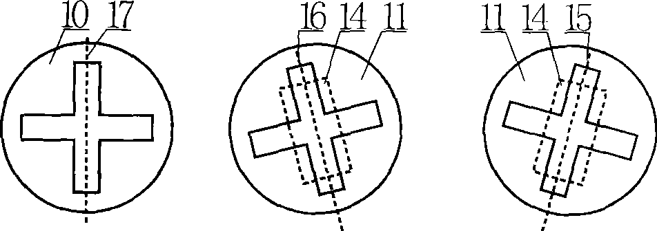
[0023] a. Divide the parallel light in the shape of a "cross" emitted by the collimator 1 into two beams of strictly parallel light through the beam splitter 2, and present two original "cross"-shaped images 10 horizontally, flat and vertically.

[0024] b. Two beams of strictly parallel light presenting two horizontal, flat and vertical original "cross"-shaped images 10 are injected into the objective lenses in the two light tubes of the optical instrument 3 under test, and projected from the eyepiece to present a "cross"-shaped image 11 After the emitted light, the two beams of light present a "cross"-shaped image 11 containing information about the parallelism of the two optical axes of the instrument under test.

[0025] c. Combining the light of the "cross"-shaped image 11 of the two optical axis parallelism inform...


PUM


Abstract

The invention discloses a method for detecting the optically biaxial parallelism of an optical instrument on a digitized basis and a device thereof, wherein, the method comprises the following steps: dividing parallel light with a cross-shaped image emitted by a collimator into two beams of light which are strictly parallel to each other by a light dividing device; irradiating the two beams of light to the left eyepiece and the right eyepiece of an optical instrument to be measured respectively; emitting the light from the eyepieces of the instrument; then, synthesizing the light through a fusion device to generate an image with two cross-shaped patterns; and transmitting the synthetic image to a computer for processing by a camera probe. The inclined angle of the two images and the non-superposition degree of the two cross-shaped patterns serve as quantitative indexes in parallelism judgment; and the two images are superposed after the tilt correction of the image shown in the instrument to further judge the parallelism of the two optical axes of the instrument. By adopting the method, the invention has the advantages that not only the workload is reduced; but also the operating time is shortened; and the precisions of detection and correction are greatly improved as the quantitative indexes in parallelism judgment can be obtained through the computer.

Description

technical field [0001] The invention relates to a method for detecting the performance of an optical instrument, in particular to a method for digitally detecting the parallelism of two optical axes in an optical instrument with double lens barrels and its equipment . Background technique [0002] The existing manual detection method uses a dual optical axis calibration instrument for detection. The detection method is: aim the instrument under test at the cross target, adjust the diopter screw to see the target clearly, move the optical axis instrument so that the left lens barrel is aligned with the cross target, Then check to see if the cross targets on the right and left lens barrels are within the rectangular frame. If so, it indicates that the indicators meet the requirements. This method can only be a qualitative inspection. Since the detection method adopts a manual operation mode, the input workload is large, the operation time is long, and the accuracy of detectio...

Claims


Application Information

Patent Timeline
Patent Type & Authority Applications(China)
IPC IPC(8): G01B11/27
Inventor 白剑新华良洪何凡吴修生宋海发鲁刚林庆艇
Owner 中国人民解放军92854部队军械修理厂
Learn More