
Perforating device for automatic cloth cutter

The technology of a punching device and a cutting machine is applied in the cutting of textile materials, textiles and papermaking, metal processing, etc. It can solve the problems of inconvenient disassembly, inconvenient disassembly, and low punching accuracy, so as to improve life, reduce wear, Positioning precise effects

Inactive Publication Date: 2009-06-24
SHAGNHAI YIN SCI&TECH CO LTD
View PDF0 Cites 17 Cited by
  • Summary
  • Abstract
  • Description
  • Claims
  • Application Information

AI Technical Summary

Problems solved by technology

When the drilling equipment needs maintenance, it is inconvenient to disassemble and difficult to maintain; and because of the overall technical equipment structure of the drilling equipment, the precision of drilling is not high, and high-precision work cannot be completed
Therefore, the problems of adopting this technology are: inconvenient disassembly and difficult maintenance; the punching accuracy is not high, and the work efficiency cannot be improved.

Method used


Image

  • Perforating device for automatic cloth cutter
  • Perforating device for automatic cloth cutter

Examples


Embodiment Construction

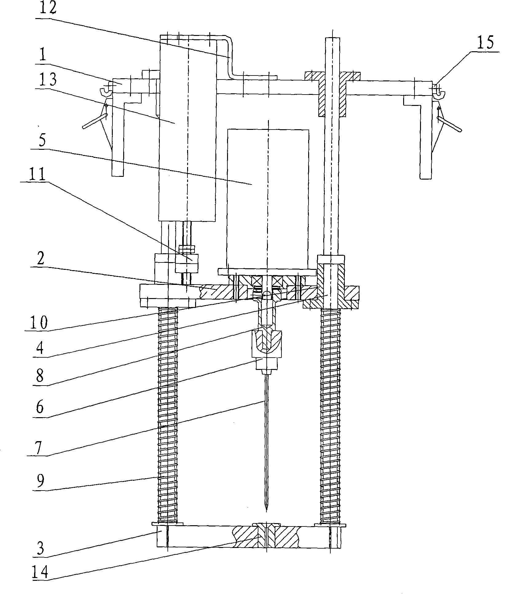
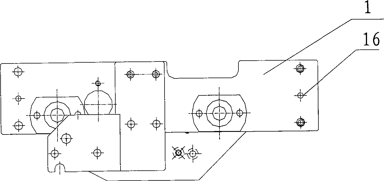
[0020] Such as figure 1 , figure 2 As shown, the present invention is used for the punching device of the automatic cutting machine, comprises the upper plate 1, the middle plate 2 and the lower plate 3 that are horizontally arranged in parallel, and there are two longitudinally running through between the upper plate 1, the middle plate 2 and the lower plate 3. The slide rail shaft 4 arranged in parallel, the motor 5 is arranged on the middle plate 2, the drill chuck 6 and the punching needle 7 are arranged vertically downward, the drill chuck 6 is connected with the motor 5 through the bearing shaft 8, and the middle plate 2 is arranged along the The slide rail shaft 4 slides up and down, and a spring 9 is sleeved on the slide rail shaft 4 between the middle plate 2 and the lower plate 3 .

[0021] There are two linear slide rail seats 10 on the middle plate 2, and the two slide rail shafts 4 respectively pass through the linear slide rail seats 10, and a retaining ring 11...


PUM


Abstract

The invention discloses a punching device used for an automatic cutting machine. The device comprises an upper board, a middle board and a lower board which are arranged transversely and parallelly; two slide rail shafts arranged parallelly run through the upper board, the middle board and the lower board longitudinally; a motor is arranged on the middle board, and a drill chuck and a punching pin are arranged vertically downwards; the drill chuck is connected with the motor through a bearing shaft; the middle board slides up and down along the slide rail shafts; and a spring is sheathed on the slide rail shaft between the middle board and the lower board. The middle board is provided with two straight line slide rail seats; the two slide rail shafts run through the straight line slide rail seats respectively; and baffle rings are arranged on the straight line slide rail seats. The device has the advantages of convenient maintenance, high punching precision, exact positioning and high work efficiency.

Description

technical field [0001] The invention relates to a punching device, in particular to a punching device for an automatic cutting machine. Background technique [0002] The punching device is a device that can punch holes and position materials during the work of an automatic cutting machine. At present, the traditional punching device is to install the punching equipment on the machine head as a whole, which is a non-detachable connection. When the punching equipment needs to be maintained, it is very inconvenient to disassemble and difficult to maintain; and because of the overall technical equipment structure of the punching equipment, the precision of punching is not high, and high-precision work cannot be completed. Therefore, the problems of adopting this technology are: disassembly is inconvenient, maintenance is difficult; punching precision is not high, and work efficiency cannot be improved. Thereby be badly in need of a kind of punching device that can maintain con...

Claims


Application Information

Patent Timeline
Patent Type & Authority Applications(China)
IPC IPC(8): B26F1/24D06H7/00
Inventor 尹智勇
Owner SHAGNHAI YIN SCI&TECH CO LTD
Learn More