Radio communication device and radio communication method
A wireless communication device and signal transmission technology, applied in multiplex communication, modulated carrier system, transmission system, etc., can solve the problem of low correlation of antenna received signals
- Summary
- Abstract
- Description
- Claims
- Application Information
AI Technical Summary
Problems solved by technology
Method used
Image
Examples
no. 1 example
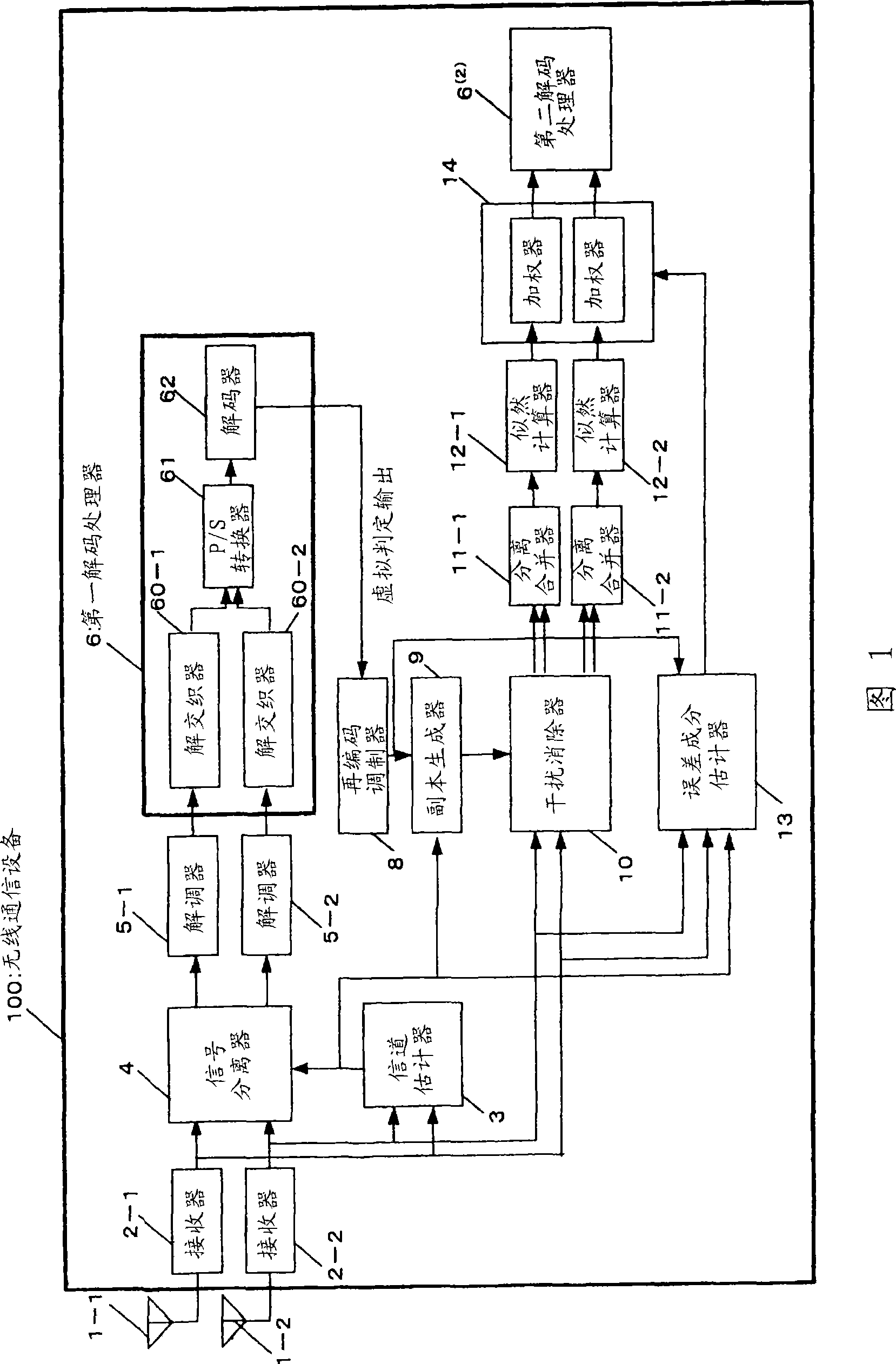
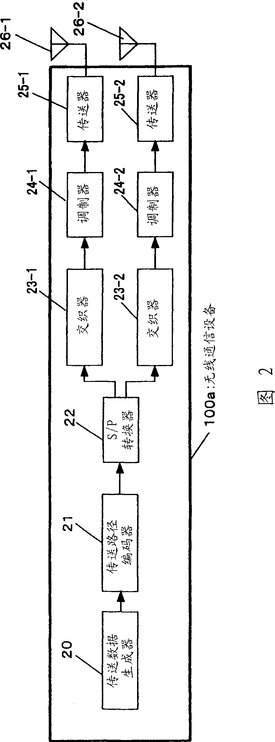
[0116] figure 1 is a diagram showing the configuration of the wireless communication device 100 in the first embodiment of the present invention. exist figure 1 Only the receiving configuration is displayed in the wireless communication device 100 of the figure 2 The transmission configuration is displayed in the wireless communication device 100a of . The reception configuration in the embodiment is a configuration in which iterative decoding is performed using a Parallel Interference Canceller (PIC). The following will follow figure 1 with 2 The operation is discussed in the order:
[0117] First, refer to figure 2 The transmission operation of the wireless communication device 100a is discussed. The wireless communication device 100a performs spatial multiplexing transmission of M transmission sequences from a plurality (M, M>1) of antennas 26-1 to 26-M (hereinafter will be referred to as spatial multiplexing streams) . figure 2 The configuration of the wireless...
no. 2 example
[0203] Figure 9 is a diagram showing the configuration of the wireless communication device 200 in the second embodiment of the present invention. exist Figure 9 Only the receiving configuration is shown in the wireless communication device 200, and in Figure 10 The transmission configuration is shown in the wireless communication device 201 of . In the first embodiment, a transmission and reception configuration for performing space multiplexing transmission is shown, and a second embodiment shows a case where M=1 in the first embodiment, no space is performed Transmit and receive configurations for multiplexed transports. The following will use Figure 9 , 10 The operations are discussed in order.
[0204] First, refer to Figure 10 The transmission operation of the wireless communication device 201 is discussed. The wireless communication device 201 transmits a transmission sequence (hereinafter will be referred to as a transmission stream) from an antenna 26 . ...
no. 3 example
[0257] Figure 4 is a diagram showing the configuration of the wireless communication device 100b in the third embodiment of the present invention. exist Figure 4 In the wireless communication device 100b of , only the receiving configuration is shown, and the transmitting configuration is the same as figure 2 This configuration of the wireless communication device 100a shown in is the same, and therefore the transmission operation will not be discussed again.
[0258] As a reception configuration in this embodiment, it shows a configuration in which iterative decoding is performed using a parallel interference canceller (PIC). The third embodiment differs from the first embodiment in that a wireless communication device has an error component estimator 15 for estimating an error component based on an input signal, which is different from the error component estimator 13 in the first embodiment. That is, error component estimator 15 estimates error components based on the...
PUM
 Abstract
Description
Claims
Application Information
 - R&D
- Intellectual Property
- Life Sciences
- Materials
- Tech Scout
- Unparalleled Data Quality
- Higher Quality Content
- 60% Fewer Hallucinations
Browse by: Latest US Patents, China's latest patents, Technical Efficacy Thesaurus, Application Domain, Technology Topic, Popular Technical Reports.
© 2025 PatSnap. All rights reserved.Legal|Privacy policy|Modern Slavery Act Transparency Statement|Sitemap|About US| Contact US: help@patsnap.com


