
Assemblies in the printing unit of a rotary press

A combined device, printing machine technology, applied in the direction of rotary printing machine, lithographic rotary printing machine, printing machine roll coat, etc., to achieve good ink absorption, high wear resistance and aging resistance, good ink release effect

Inactive Publication Date: 2009-06-03
KOENIG & BAUER AG
View PDF10 Cites 4 Cited by
  • Summary
  • Abstract
  • Description
  • Claims
  • Application Information

AI Technical Summary

Problems solved by technology

The disadvantage of this type of anilox roller is that, especially in the wet offset printing process, the shell surface made of steel can produce faults in the ink delivery after a short running time, because this shell surface is prone to quickly lead to Runs without ink

Method used


Image

  • Assemblies in the printing unit of a rotary press
  • Assemblies in the printing unit of a rotary press
  • Assemblies in the printing unit of a rotary press

Examples


Embodiment Construction

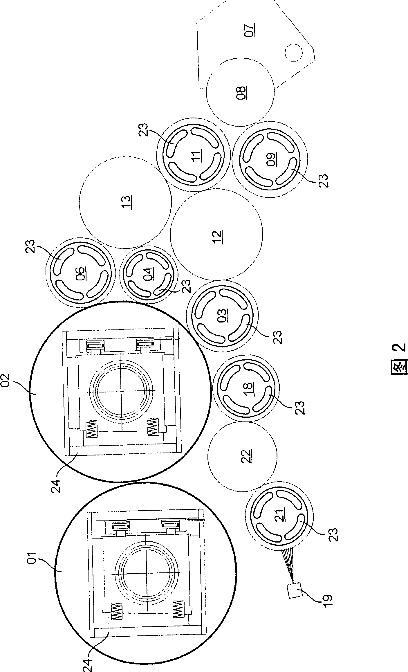
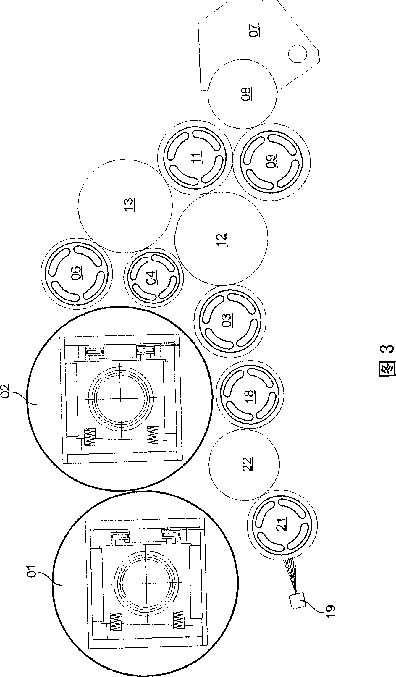
[0032] FIG. 1 shows an example of a part of a printing unit of a rotary printing press. In the example shown, the rotary printing press operates in a wet offset process. Its application is especially envisioned in newspaper printing. The printing unit has at least one transfer cylinder 01 as printing unit cylinder 01 ; 02 and a forme cylinder 02 cooperating with the transfer cylinder 01 . With each rotation of the transfer cylinder 01 , at least one printed image is produced on a printing material (not shown), preferably on a material web, in particular a paper web. In the operating situation of the printing unit as shown in FIG. 1 , at least one inking unit and one dampening unit are located close to the plate cylinder 02 .

[0033] The inking unit has a plurality, preferably at least three, inking rollers 03 ; 04 ; 06 , which abut against the plate cylinder 02 during the production process of the operation of the rotary printing press. A plurality of rollers 09 ; 11 ; 12 ...


PUM


Abstract

The invention relates to assemblies in a printing unit of a rotary press, each assembly comprising at least one plate cylinder (02), three ink form rollers (03,04, 06), two vibrator rollers (12,13) and an ink separator roller (11). Both vibrator rollers (12,13) are applied directly to the ink separator roller (11) and one of the ink form rollers is applied to both one of the vibrator rollers and the plate cylinder, the remaining two ink form rollers being applied both to the other vibrator roller and the plate cylinder. The plate cylinder (02) is covered with several forms and / or the upper ink form roller (06) is located in such a way that a horizontal tangent (T06) to the circumference of said ink form roller lies at a vertical distance (a06) of at least 50mm from a horizontal tangent (T06) to the circumference of the plate cylinder.

Description

technical field [0001] The invention relates to a combination in a printing unit of a rotary printing press according to the preamble of claim 1 or 3 . Background technique [0002] DE 44 39 144 A1 / C2 discloses an inking unit for a rotary printing press with a fountain roller for absorbing ink from an ink reservoir and a plurality of inking rollers for applying ink to the cylinder of the printing unit , wherein, an ink flow separation roller that divides the ink flow from the ink fountain roller into a main flow and a side flow is provided, wherein, in the main flow and the side flow, an ink flow separation roller is arranged to transport ink from the ink flow separation roller to at least An inking roller for the ink form roller. The ink roller column between the ink fountain roller and the ink flow separation roller consists of four ink rollers arranged in a row and is therefore relatively long, so that if the ink form roller needs to apply a defined amount of ink to the ...

Claims


Application Information

Patent Timeline
Patent Type & Authority Applications(China)
IPC IPC(8): B41F7/26B41F13/30B41F31/00B41F31/04B41F31/26B41F31/36B41F31/30B41N7/06B41F7/12B41F27/12
Inventor 乔治·施奈德贝尔恩特·库尔特·马舒赫
Owner KOENIG & BAUER AG
Learn More