LCD splicing display device
A technology for splicing display and screen, applied in the field of LCD display, to achieve the effect of eliminating panel borders, easy to implement, and simple device principle
- Summary
- Abstract
- Description
- Claims
- Application Information
AI Technical Summary
Problems solved by technology
Method used
Image
Examples
Embodiment 1
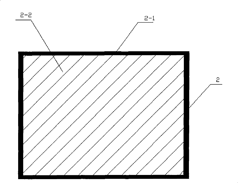
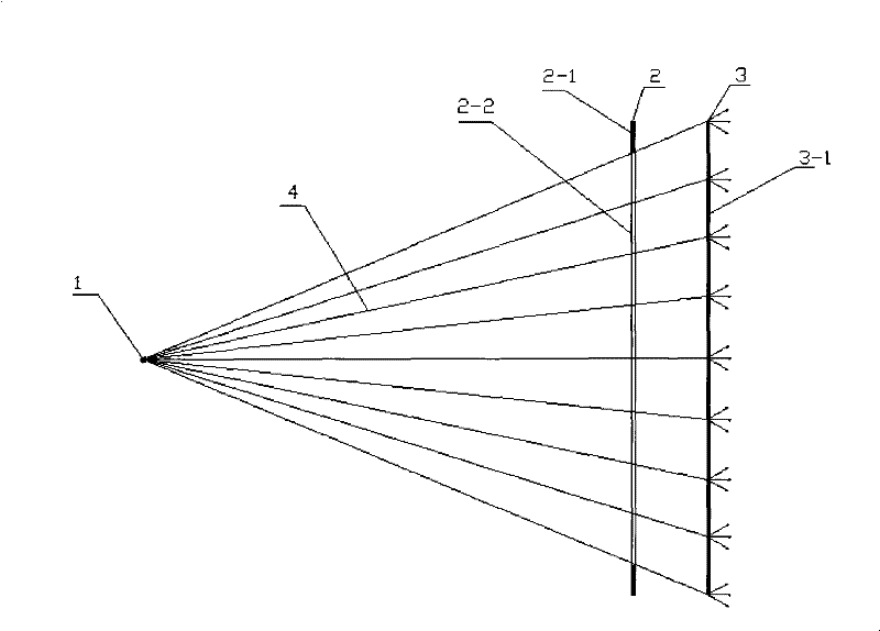
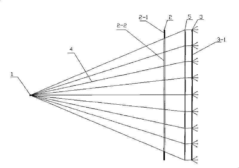
[0033] An LCD splicing display device in this embodiment, such as figure 1 As shown, the LCD panel 2 is surrounded by a panel frame 2-1, and the middle part is a picture 2-2. The structure of the LCD splicing display device is as follows: figure 2 As shown, it consists of a point light source 1, an LCD panel 2 and a rear projection screen 3 arranged in sequence according to the optical path, wherein the LCD panel 2 is surrounded by a panel frame 2-1, and the middle part is a picture 2-2; the point light source 1 is placed on the picture 2 -2 on the vertical center line; wherein the projected picture 3-1 on the rear projection screen 3 is the projected picture obtained after the picture 2-2 on the LCD panel is projected by a point light source.
[0034] Such as image 3 As shown, in order to improve the display effect on the rear projection screen 3 , a collimating lens 5 for collimating the light beam 4 incident on the rear projection screen 3 may be provided between the L...
Embodiment 2
[0038] An LCD splicing display device in this embodiment, such as Figure 5 As shown, there is a panel frame 2-1 around the LCD panel 2, a plurality of discrete pictures 2-2 in the middle part, and a picture interval 2-3 between any two adjacent pictures 2-2. The structure of the LCD splicing display device is as follows: Figure 6 As shown, it consists of a point light source 1, an LCD panel 2 and a rear projection screen 3 arranged in sequence according to the optical path, wherein the LCD panel 2 is surrounded by a panel frame 2-1, and the middle part is a plurality of discrete screens 2-2; each discrete screen A point light source 1 is placed on the vertical center line of 2-2; the projected picture 3-1 on the rear projection screen 3 is the projected picture obtained after the picture 2-2 on the LCD panel is projected by the point light source.
[0039] The width of the frame interval 2-3 is greater than or equal to twice the width of the frame 2-1 of the LCD panel.
[...
Embodiment 3
[0044] This embodiment is an LCD large-screen splicing display system, which is formed by splicing the LCD splicing display devices of the above-mentioned embodiment 1 or embodiment 2, respectively as follows Figure 9 and Figure 10 As shown, the projection screens 3-1 of any two adjacent LCD splicing display devices on the rear projection screen 3 are connected to each other to form an overall large projection screen, which completely blocks the splicing screen 6 generated by the LCD splicing, thus forming an infinite stitching display system.
[0045] The LCD splicing display devices on the above-mentioned LCD large-screen splicing display system use one rear projection screen independently, or multiple LCD splicing display devices share one rear projection screen.
PUM
 Abstract
Description
Claims
Application Information
 - R&D Engineer
- R&D Manager
- IP Professional
- Industry Leading Data Capabilities
- Powerful AI technology
- Patent DNA Extraction
Browse by: Latest US Patents, China's latest patents, Technical Efficacy Thesaurus, Application Domain, Technology Topic, Popular Technical Reports.
© 2024 PatSnap. All rights reserved.Legal|Privacy policy|Modern Slavery Act Transparency Statement|Sitemap|About US| Contact US: help@patsnap.com


