
Flexible wiring board, method of producing the same and imaging device

A technology of wiring boards and flexible substrates, applied in the field of flexible wiring boards, which can solve the problems of maintaining folded parts and the difficulty of flexible wiring boards, etc., and achieve the effect of suppressing reaction force

Inactive Publication Date: 2009-05-27
FUJIFILM CORP
View PDF1 Cites 9 Cited by
  • Summary
  • Abstract
  • Description
  • Claims
  • Application Information

AI Technical Summary

Problems solved by technology

[0004] However, with the flexible wiring board of JP-A No. 2007-122020, it is difficult to constantly keep the folded portion at a folded angle of 90° during the assembly step

Method used


Image

  • Flexible wiring board, method of producing the same and imaging device
  • Flexible wiring board, method of producing the same and imaging device
  • Flexible wiring board, method of producing the same and imaging device

Examples


Embodiment Construction

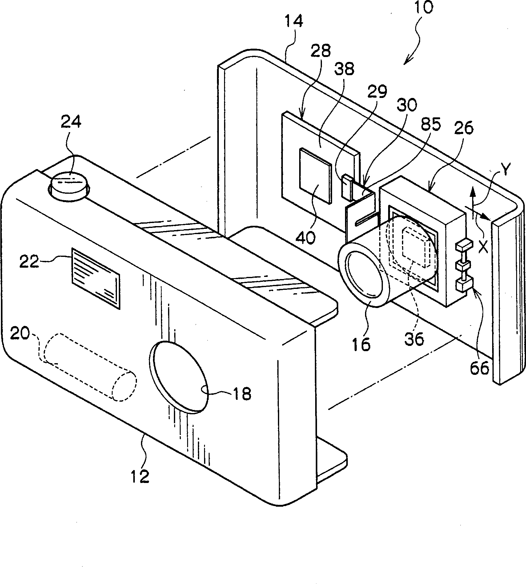
[0034] Hereinafter, a flexible wiring board and an imaging device according to a first embodiment of the present invention will be described with reference to the drawings.

[0035] figure 1 A digital video camera 10 as an imaging device is shown. The digital video camera 10 has a front cover 12 and a rear cover 14 that constitute the main body of the digital video camera 10.

[0036] The front cover 12 has an opening into which the lens 16 is inserted for forming an image of a subject. The inside of the front cover 12 is provided with: a power supply unit 20, which is used to provide power to various parts of the digital video camera 10; a flash device 22, which emits light as needed during shooting; and a switch button 24, which is used to start the imaging operation .

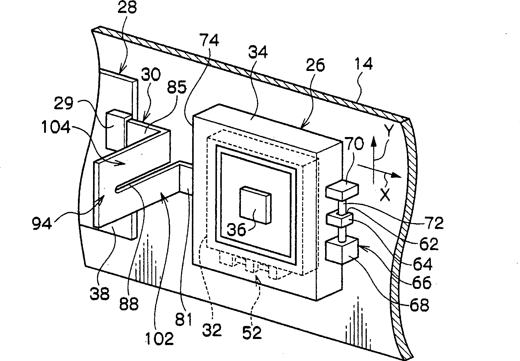
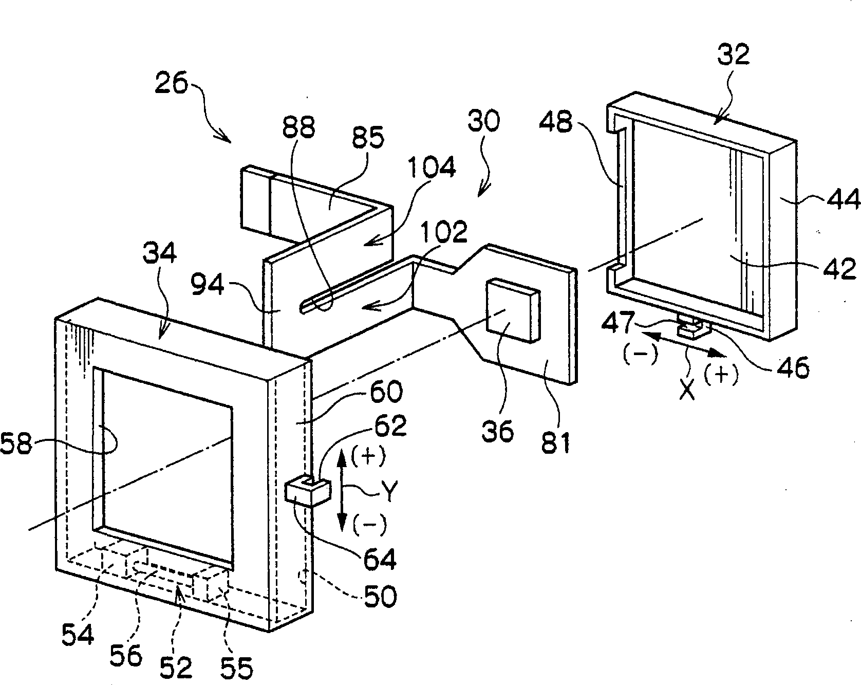
[0037] On the other hand, an imaging unit 26 having a CCD (Charge Coupled Device) 36 is provided on the inner side of the back cover 14 which receives light incident from the lens 16 and converts the light int...


PUM


Abstract

A flexible wiring board is formed with a first mounting surface, a first erected surface portion, a relay portion, a second erected surface portion and a second mounting surface. The first erected surface portion and the second erected surface portion are positioned on the same plane. The second mounting surface is fixed. When the first mounting surface is moved in the X-axis direction, the force in the X-axis direction acts on the relay portion as a force from a direction outside of the plane since the first erected surface portion and the second erected surface portion are positioned on the same plane. Therefore, the relay portion is bent and a suppressed reaction force acts on the first mounting surface and on the second mounting surface.

Description

Technical field [0001] The present invention relates to a flexible wiring board, a method of manufacturing the wiring board, and an imaging device. Background technique [0002] The digital video camera is provided with a blur correction mechanism (image stabilization mechanism) for correcting image blur caused by unexpected hand movement (camera vibration) during shooting. The blur correction mechanism works in such a way that accompanying the movement of the camera caused by the unexpected movement of the hand, the moving part supporting the imaging element or the optical element also moves, and the signal is processed by a circuit board fixed in the camera body to suppress image blur. The moving parts are moved by voice coil motors or stepping motors. [0003] Here, a flexible wiring board having a folded part (folded part) is used to electrically connect the moving part to the circuit board while suppressing the load of the movement of the moving part (for example, see JP-A N...

Claims


Application Information

Patent Timeline
Patent Type & Authority Applications(China)
IPC IPC(8): H05K1/02H04N5/225G03B17/02H04N5/232H04N5/335H04N5/351H04N5/372H04N101/00
CPCH05K1/028H05K2201/09081Y10T29/49124
Inventor 饭田晃久
Owner FUJIFILM CORP
Learn More