Active sensor element and method of determining the temperature of an active sensor element

A technology of sensor elements and source sensors, applied to devices using electric/magnetic methods, engine components, instruments, etc., can solve problems such as high impeller speed, damaged turbocharger, wrong speed signal, etc., to achieve low cost, low cost effect

Active Publication Date: 2009-05-20
CONTINENTAL AUTOMOTIVE TECH GMBH
View PDF1 Cites 6 Cited by
  • Summary
  • Abstract
  • Description
  • Claims
  • Application Information

AI Technical Summary

Problems solved by technology

If the temperature inside the semiconductor exceeds this value, it may cause the sensor to suffer irreparable damage, which may again generate a wrong speed signal, and finally may cause the impeller to rotate too high and damage the turbocharger

Method used


Image

  • Active sensor element and method of determining the temperature of an active sensor element
  • Active sensor element and method of determining the temperature of an active sensor element
  • Active sensor element and method of determining the temperature of an active sensor element

Examples


Embodiment Construction

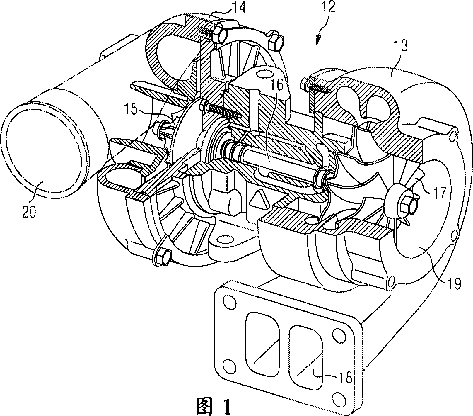
[0026] FIG. 1 shows an exhaust gas turbocharger 12 with a turbine 13 and a compressor 14 . A compressor wheel 15 is rotatably mounted in the compressor 14 and connected to a turbine shaft 16 . A turbine shaft 16 is also rotatably mounted and its other end is connected to a turbine 17 . The hot exhaust gas enters the turbine 13 from the internal combustion engine (not shown here) via the turbine inlet 18 , whereby the turbine 17 is rotated. The exhaust gas flow exits the turbine 13 through a turbine outlet 19 . The turbine 17 is connected to the compression wheel 15 via a turbine shaft. The turbine 13 thus drives the compressor 14 . Air is sucked into the compressor 14 via an air intake 21 , is compressed in the compressor 14 and delivered to the internal combustion engine via an exhaust air port 20 .

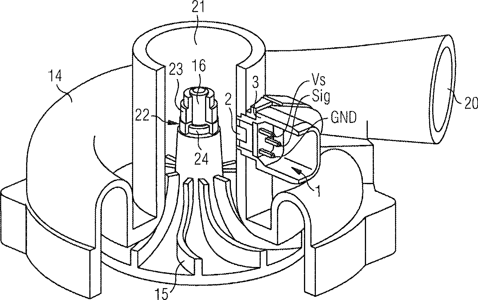
[0027] figure 2 A compressor 14 of the exhaust gas turbocharger 12 is shown with a turbine shaft 16 and a compressor wheel 15 . The compressor wheel 15 can be produced, fo...


PUM


Abstract

The invention relates to an active sensor element for recording the speed of an exhaust gas turbocharger, comprising a suppressor circuit which has at least one diode. In order to specify a device for temperature measurement at the turbocharger and in particular at the turbocharger in the region of the active sensor, the current-voltage characteristics of the diode are evaluated for determining the temperature in the sensor element.

Description

technical field [0001] The invention relates to an active sensor element according to the preamble of claim 1 and to a method for determining the temperature of an active sensor element. Background technique [0002] The power produced by the internal combustion engine depends on the amount of air and the corresponding amount of fuel that can be supplied to the internal combustion engine for combustion. In order to increase the power of an internal combustion engine, a greater amount of combustion air and fuel must be supplied to the internal combustion engine. This increase in power is achieved in naturally aspirated engines by increasing the working volume of the cylinder or by increasing the rotational speed. But substantially increasing the cylinder displacement results in a heavier, larger and therefore more expensive internal combustion engine. [0003] A technical solution that is often used to improve the efficiency of internal combustion engines is supercharging. ...

Claims


Application Information

Patent Timeline
IPC IPC(8): F01D17/06G01P3/46
CPCG01P3/488F05D2220/40F05B2220/40F01D17/06G01P3/49F02B37/12F02B39/16G01P3/46
Inventor 约翰内斯·安特马库斯·吉尔希斯特凡·海因里希塞尔久·穆雷尚
Owner CONTINENTAL AUTOMOTIVE TECH GMBH
Why Eureka
Try Eureka