
Thermal switch for heat control system of camera

A technology of thermal control system and space camera, which is applied in the camera body, camera, optics, etc., can solve the problem that the temperature of the CCD focal plane component of the detector is difficult to control, and achieve a simple structure, high reliability, and long service life. Effect

Inactive Publication Date: 2009-05-06
CHANGCHUN INST OF OPTICS FINE MECHANICS & PHYSICS CHINESE ACAD OF SCI
View PDF0 Cites 11 Cited by
  • Summary
  • Abstract
  • Description
  • Claims
  • Application Information

AI Technical Summary

Problems solved by technology

[0006] The purpose of the present invention is to propose a thermal switch for the space camera thermal control system, to overcome the disadvantage that the temperature of the detection device CCD focal plane assembly (CFPA) in the current space camera is difficult to control, and effectively ensure the stability of the space camera work

Method used


Image

  • Thermal switch for heat control system of camera
  • Thermal switch for heat control system of camera
  • Thermal switch for heat control system of camera

Examples


Embodiment Construction

[0017] The present invention will be described in further detail below in conjunction with the embodiment given with accompanying drawing.

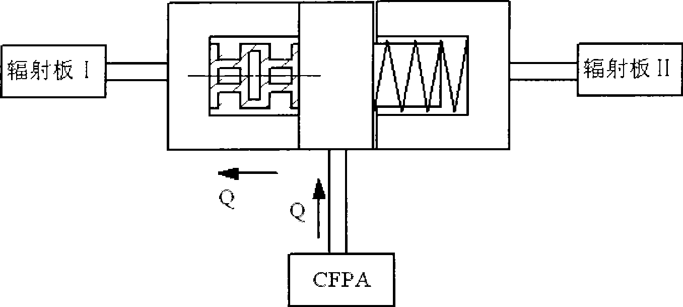
[0018] refer to figure 1 , the thermal switch used for the thermal control system of the space camera, including the left heat conduction block (1) and the right heat conduction block (3) made of Invar, which can be directed between the left heat conduction block (1) and the right heat conduction block (3) The movable heat conduction block (2) moving left and right, the telescopic rod (4) and the spring (6); the left heat conduction block (1) and the right heat conduction block (3) are all provided with a blind opening to the movable heat conduction block (2). hole, the telescopic rod (4) and the left heat conduction block (1) are arranged in the blind hole of the left heat conduction block (1) in a sliding fit, and its two ends are respectively fixedly connected to the bottom of the blind hole of the left heat conduction block (1) and t...


PUM


Abstract

The invention relates to a switch of a thermal control system for a temperature sensing device, in particular to a thermal switch of a thermal control system for a spatial camera. The thermal switch comprises a left heat conducting block, a right heat conducting block, a movable heat conducting block which can transversally move between the left heat conducting block and the right heat conducting block, a telescopic rod made of materials with the thermal expansion coefficient larger than that of the left heat conducting block, the right heat conducting block and the movable heat conducting block, and a spring. Both the left heat conducting block and the right heat conducting block are provided with blind holes with openings towards the movable heat conducting block; the telescopic rod and the left heat conducting block are arranged in the blind hole of the left heat conducting block in a sliding fit manner; and the spring is arranged in the blind hole of the right heat conducting block. The movable heat conducting block is achieved to be respectively in crossed contact with the left heat conducting block and the right heat conducting block to change a thermal conducting channel through the thermal expansion and the cold shrinkage of the telescopic rod. The thermal switch has the advantages of simple structure, high reliability and long service life, and can achieve the automatic temperature control function of the temperature sensing device.

Description

technical field [0001] The invention relates to a thermal control system switch applied to temperature sensitive devices, in particular to a thermal control component that can be used as a variable heat dissipation channel for space optical remote sensor CCD focal plane components and the like. Background technique [0002] At present, most space cameras use CCD as the detection device. However, it is sensitive to temperature. Excessively high temperature levels and excessive temperature fluctuations will increase the dark current and thermal noise of the CCD device, resulting in a decrease in signal-to-noise ratio and affecting image quality. Therefore, it is the goal of CFPA thermal design to ensure that the CCD focal plane assembly (CFPA) is at a lower temperature level and within a smaller temperature fluctuation range. [0003] Due to the space environment where the camera is located, as well as the requirements of optical and mechanical structures, CFPA is installed i...

Claims


Application Information

Patent Timeline
Patent Type & Authority Applications(China)
IPC IPC(8): G03B17/55
Inventor 吴清文韩冬杨成禹陈立恒黎明葛任伟
Owner CHANGCHUN INST OF OPTICS FINE MECHANICS & PHYSICS CHINESE ACAD OF SCI
Learn More