
Fully-coupled dry hole acoustic wave test probe

A sonic probe, fully coupled technology, applied in the direction of material analysis, measuring devices, instruments, etc. using sound waves/ultrasonic waves/infrasonic waves, can solve the problem of failure to solve the coupling between the pressurized water bladder and the hole wall, poor coupling of the sonic probe, Acoustic detection is difficult to carry out and other problems, to achieve stable and reliable test data, meet the needs of high-intensity continuous work, and save water

Active Publication Date: 2009-04-29
CHANGJIANG GEOPHYSICAL EXPLORATION & TESTING WUHAN CO LTD
View PDF1 Cites 12 Cited by
  • Summary
  • Abstract
  • Description
  • Claims
  • Application Information

AI Technical Summary

Problems solved by technology

[0003] Acoustic detection of transmitting and receiving probes generally achieves good coupling with the hole wall through the medium in the hole---water. The application of this technology in dry holes is greatly limited. In engineering practice, dry holes that need to be detected often encounter , usually acoustic testing is performed in dry holes due to the poor coupling between the acoustic probe and the hole wall, which makes it difficult to perform acoustic testing, which greatly limits the scope of this technical method to solve engineering problems
In order to solve this kind of problem, Chinese patent publication number ZL2006 2 0163832.6, titled as a new type of dry-hole acoustic wave test probe, it proposes a method of putting a pressurized water bag on the outer surface of the sound wave probe. The air hole is limited to satisfying the discharge of the air in the pressurized water bag, so as to achieve only in-coupling, but it fails to solve the coupling between the pressurized water bag and the hole wall (ie, out-coupling), resulting in unsatisfactory test results

Method used


Image

  • Fully-coupled dry hole acoustic wave test probe

Examples


Embodiment Construction

[0013] The fully coupled dry-hole acoustic wave probe of the present invention will be further described in detail below with reference to the accompanying drawings.

[0014] see Attachment

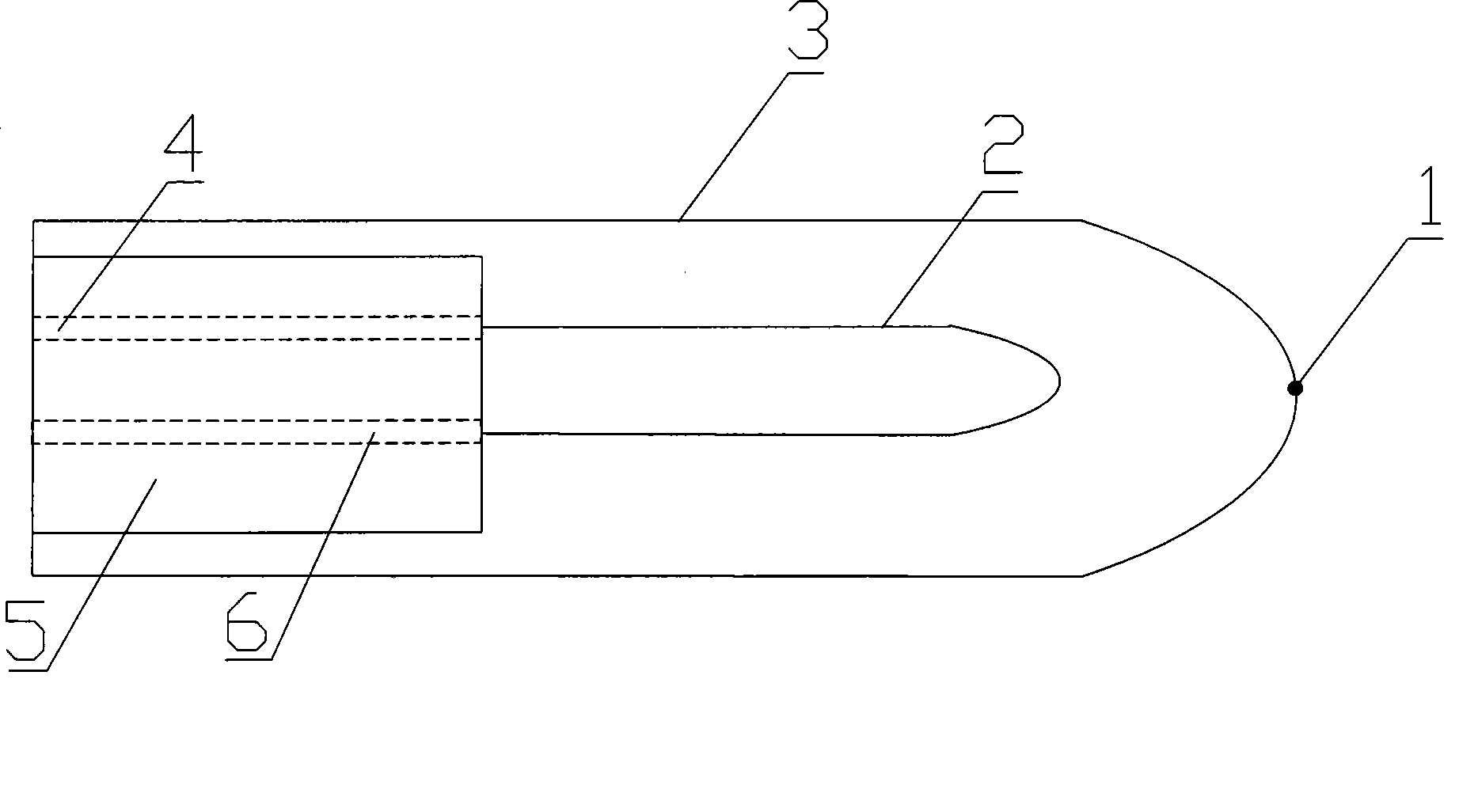
[0015] The fully coupled dry-hole acoustic probe consists of a pressurized water bladder 3, an acoustic probe 2, a water inlet pipe and a connecting device 5. The pressurized water bladder 3 is made of styrene-butadiene rubber, and the pressurized water bladder 3 is cylindrical. One end of the bladder 3 is open and the other end is closed. On the top of the closed end of the pressurized water bladder 3, there is a vent hole 1, the diameter of the vent hole 1 is ≦1mm, and the end of the acoustic wave probe 2 is provided with a connecting device 5. The connecting device 5 is provided with a water inlet channel 4 and a cable channel 6 , the pressurized water bag 3 is set outside the acoustic wave probe 2 , and the opening end of the pressurized water bag 3 is located on the connecting device...


PUM


Abstract

The invention relates to a full coupled test probe for dry hole sound wave, and belongs to the field of nondestructive examination equipment manufacture of engineering. The full coupled test probe for the dry hole sound wave comprises a sound wave probe and a pressurizing water bag, wherein the top at one sealed end of the pressurizing water bag is provided with a vent hole of which the diameter is not more than 1 millimeter. An end part of the sound wave probe is provided with a connecting device; and the pressurizing water bag is sleeved outside the sound wave probe. Air in the pressurizing water bag can be directed exhausted by the vent hole; and the pressurizing water bag is filled with water at the same time to ensure internal coupling between the sound wave probe and the pressurizing water bag. The vent hole at the top of the pressurizing water bag has double uses, namely, after the air is exhausted, the vent hole continuously keeps continuous small amount of spilling water, so as to solve coupling (external coupling) between the outer wall of the pressurizing water bag and the wall of the hole. The test probe realizes full coupling of the sound wave prove, the pressurizing water bag and the wall of the hole so that the tested data are stable and reliable, and meets the requirement of rapid detection.

Description

technical field [0001] The invention relates to a fully coupled dry-hole acoustic wave test probe, which belongs to the field of engineering non-destructive testing equipment manufacturing. Background technique [0002] Acoustic wave testing is one of the elastic wave testing methods. This method transmits sound waves to the medium (rock, rock mass, concrete structure) by means of electromagnetic excitation, and receives the sound wave modulated by the physical characteristics of the medium at a certain spatial distance. Through observation and Analyze acoustic parameters such as propagation velocity, amplitude, and frequency of sound waves in different media, and solve related problems in geotechnical engineering. [0003] Acoustic detection of transmitting and receiving probes generally achieves good coupling with the hole wall through the medium in the hole---water. The application of this technology in dry holes is greatly limited. In engineering practice, dry holes that...

Claims


Application Information

Patent Timeline
Patent Type & Authority Applications(China)
IPC IPC(8): G01N29/24G01N29/28
Inventor 张建清张智刘方文陆二男陈敏余才盛熊永红刘润泽曾凡卿李文忠胡志虎况碧波王国利刘鸿兴谢建虹詹建生朱应红张汉泉吴礼松马冠群喻维钢文志祥程含发金润新赵凌李道永
Owner CHANGJIANG GEOPHYSICAL EXPLORATION & TESTING WUHAN CO LTD
Learn More