
Ascending power control method

A power control and power technology, applied in the direction of transmission control/equalization, can solve the problems of low power control accuracy, waste of NodeB and RNC processing resources, etc., and achieve the effect of saving processing resources

Inactive Publication Date: 2009-04-08
POTEVIO INFORMATION TECH CO LTD
View PDF2 Cites 13 Cited by
  • Summary
  • Abstract
  • Description
  • Claims
  • Application Information

AI Technical Summary

Problems solved by technology

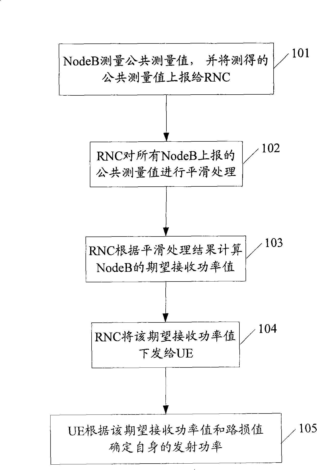
[0028] It can be seen from the above scheme that the UE obtains the PRX based on the public measurement value DPCHdes when, due to figure 1 The shown UE obtains PRX based on public measurements DPCHdes The process is long, usually takes hundreds of milliseconds to several seconds, and environmental factors change quickly, the PRX received by the UE DPCHdes It can no longer reflect the environmental factors at this time, which makes the accuracy of uplink power control lower
Moreover, using figure 1 The method shown performs uplink power control. Since the UE needs to send messages between the NodeB and the RNC, and between the RNC and the UE each time, processing resources of the NodeB and the RNC are also wasted.

Method used


Image

  • Ascending power control method
  • Ascending power control method

Examples


no. 1 approach

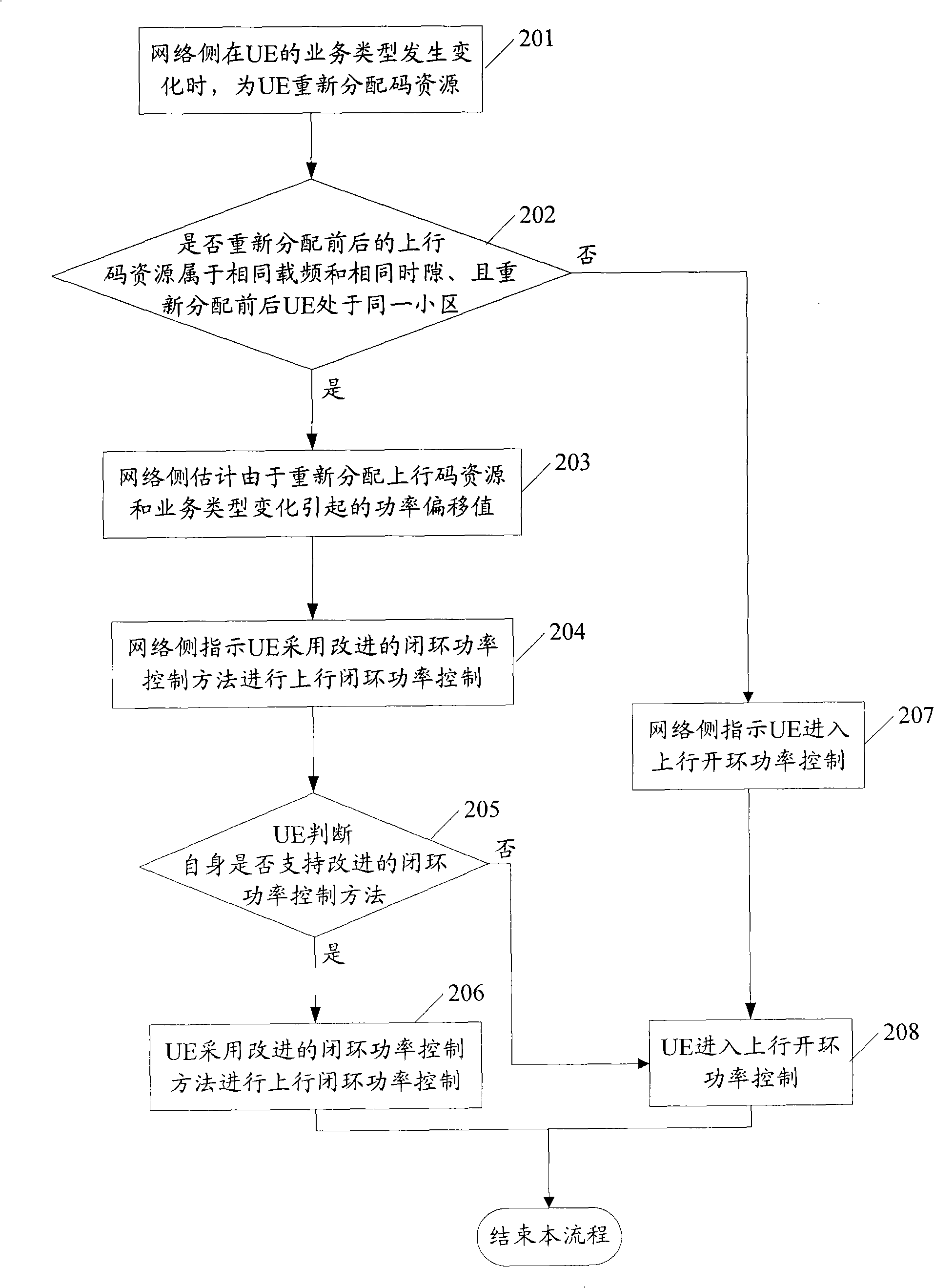
[0067] In this embodiment, the first power offset value Δ caused by reallocation of uplink code resources is estimated respectively λ and the second power offset value Δ due to the change of service type priority , UE adds Δ to the current transmit power value λ and Δ priority 1. Using the obtained result as the initial power value to perform uplink closed-loop power control. Due to Δ λ It reflects the difference between the power value requirements of code resources after reallocation and the power value requirements of code resources before reallocation, Δ priority It reflects the difference between the power value requirements of the service type after the change and the power value requirement of the service type before the change. Therefore, Δ λ with Δ priority The summed value of is used as the power offset value caused by the reallocation of uplink code resources and the change of service type.

[0068] Estimated Δ λ The method can be: simulate the power value co...

no. 2 approach

[0072] This implementation mode proposes an engineering replacement method for estimating the power offset value caused by reallocation of uplink code resources and service changes. Specifically: the network side obtains the initial target signal-to-interference ratio Initial_UL_Target_SIR and the output of the outer loop power control after reallocation of code resources. The current target signal-to-interference ratio Current_UL_Target_SIR output by the outer loop power control before reallocating code resources, and the difference obtained by subtracting Current_UL_Target_SIR from Initial_UL_Target_SIR is the power offset value caused by reallocating uplink code resources and service changes.

[0073] Among them, Initial_UL_Target_SIR reflects the UE's new service type and user priority requirements for the UE's signal-to-interference ratio after re-allocation of code resources, thereby reflecting the requirements for UE transmit power; The requirements of the old service ty...


PUM


Abstract

The embodiment of the invention discloses an uplink power control method which comprises: a network side redistributes code resources for a user device UE when the service type of the UE is changed. The method also comprises; when the uplink code resources before and after redistribution belong to the same carrier frequency and the same timeslot and when the UE before and after redistribution is arranged in the same area, the network side estimates the power excursion value caused by redistributing the uplink code resources and the changing of the service types and transmits the estimated power excursion value to the UE; the UE adds the power excursion value on the current emission power value and takes the obtained result as an initial power value for carrying out uplink closed loop power control. The method can be applied to leading the UE not to enter uplink open loop power control when the service changes, thereby improving the precision of the uplink power control.

Description

technical field [0001] The present invention relates to the technical field of communication power control, in particular to an uplink power control method. Background technique [0002] Power control is one of the key technologies for resource allocation and interference management in a communication system, and it is divided into uplink power control and downlink power control. Among them, the effective uplink power control method can reduce the transmission power of the user terminal (UE) on the premise of meeting the user's communication quality requirements, thereby reducing the interference between each UE, prolonging the standby time of the UE, and increasing the capacity of the communication system . [0003] Currently, in the TD-SCDMA communication system, uplink power control methods include an open-loop power control method, a closed-loop power control method and an outer-loop power control method. [0004] When the connection between the NodeB and the UE is not...

Claims


Application Information

Patent Timeline
Patent Type & Authority Applications(China)
IPC IPC(8): H04B7/005
Inventor 田阳史满姣
Owner POTEVIO INFORMATION TECH CO LTD
Learn More