
Optical lens assembly

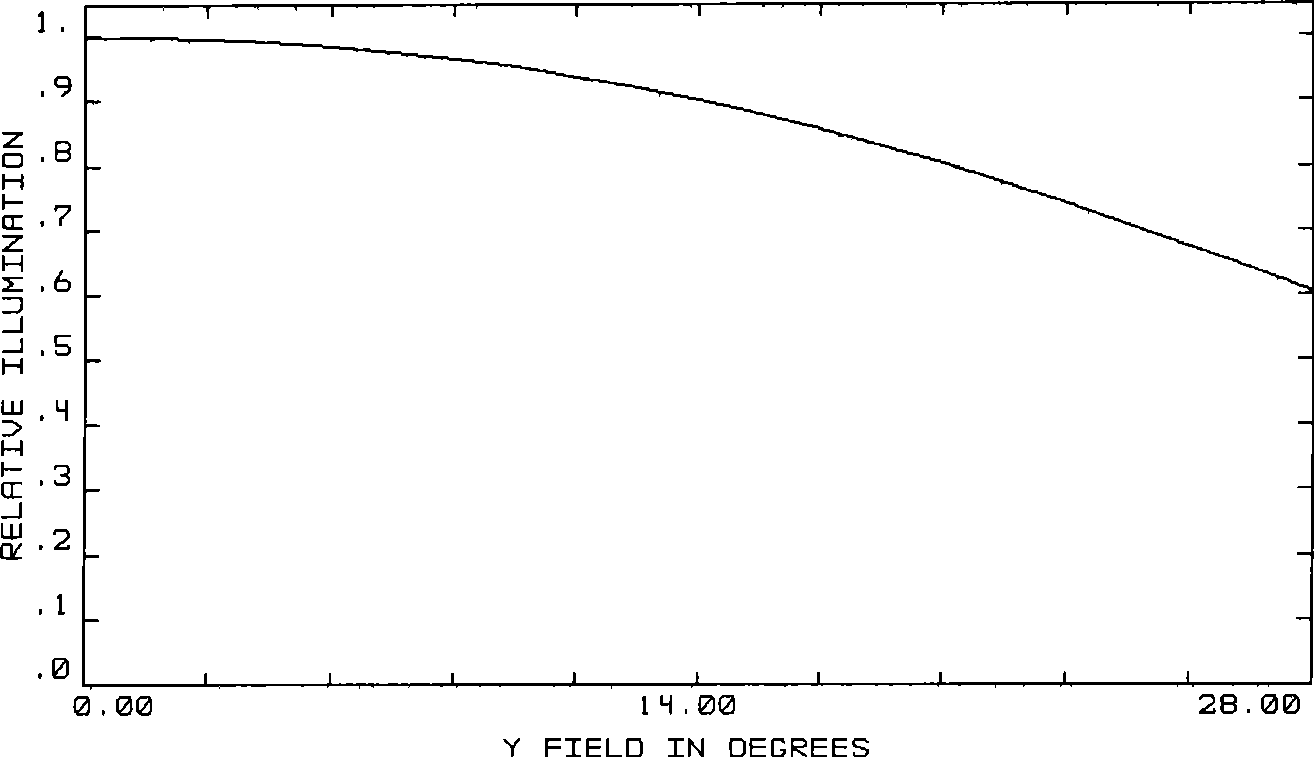
A technology of optical lenses and components, applied in the direction of optical components, optics, instruments, etc., to achieve the effects of eliminating aberrations, large relative illuminance, and simplifying the structure of lens components

Active Publication Date: 2009-04-01
BYD SEMICON CO LTD
View PDF0 Cites 0 Cited by
  • Summary
  • Abstract
  • Description
  • Claims
  • Application Information

AI Technical Summary

Problems solved by technology

However, while achieving high pixels, it is necessary to keep the mobile phone thin, light and small, which brings great challenges to the design of optical lens components.

Method used


Image

  • Optical lens assembly
  • Optical lens assembly
  • Optical lens assembly

Examples


Embodiment Construction

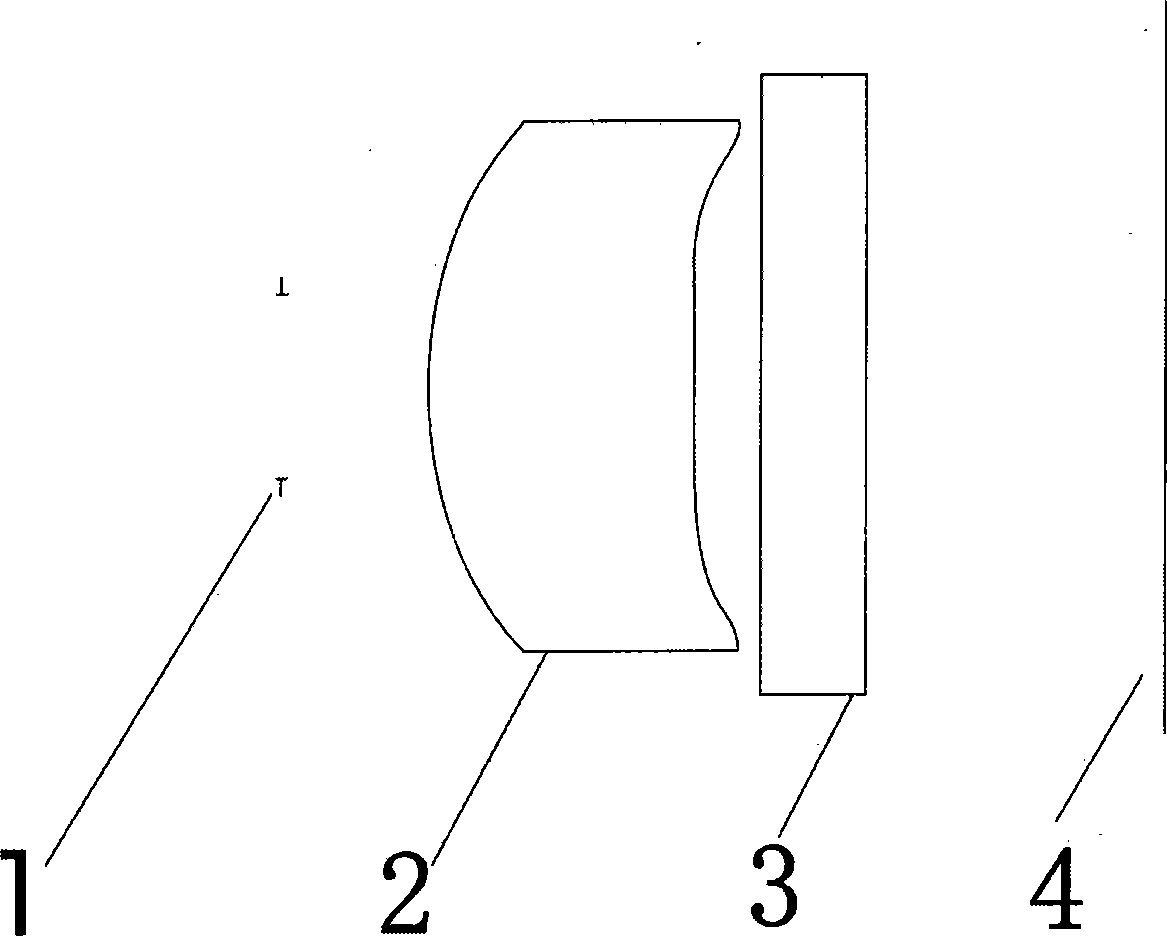
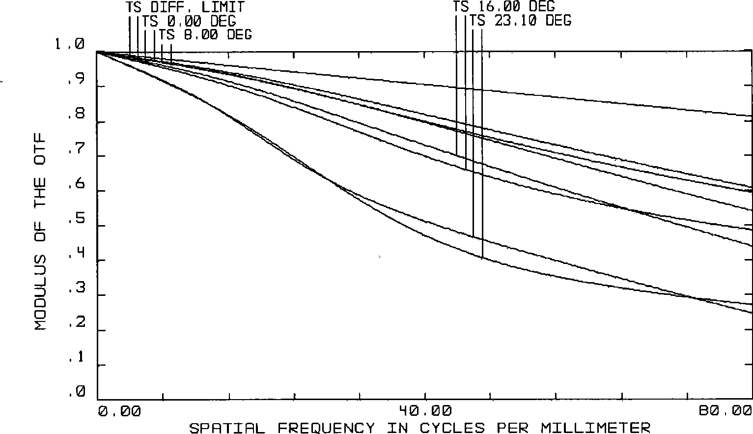
[0020] like Figure 1 to Figure 12 As shown, the optical lens assembly of the present invention includes a lens 1, a fixed diaphragm 2 and an optical filter 3, the fixed diaphragm 2 is located in front of the lens 1, and the optical filter 3 is located between the lens 1 and the imaging surface 4, so The lens 1 includes a first surface close to the object side and a second surface close to the image side, the first and second surfaces are aspherical, and the surface shape formula is:

[0021] z = cr 2 1 + 1 - ( 1 + k ) c 2 r 2 + a 1 ...


PUM


Abstract

The invention provides an optical lens component, comprising a lens, a fixed diaphragm and a filter; the lens comprises a first surface close to the object and a second surface close to the image; the first surface and the second surface are non-spherical surfaces; the surface formula is that z is equal to cr<2> / (1+1-(1+k)c<2>r<2>)+a1r<2>+a2r<4>+a3r<6>+a4r<8>+a5r<10>+a6r<12>; wherein, z is z coordinate values of all points on the non-spherical surface; r is y coordinate values of all points on the non-spherical surface; c is the curvature of the vertex of the non-spherical surface; R is the curvature radius of the vertex of the non-spherical surface; k is secondary curved surface coefficient; a1, a2, a3, a4, a5 and a6 are non-spherical surface coefficients; R is less than 2.3 and more than -2.1; k is less than -1 and more than -2.11; a1 is less than 4.5 and more than 0.2; a2 is less than 2.1 and more than -6.8; a3 is less than 18.3 and more than -12.6; a4 is less than 50.6 and more than -36.8; a5 is less than 50.8 and more than -104.7; a6 is less than 85 and more than -34.1; the imaging quality can be improved and the lens cost can be reduced by adopting one non-spherical eyeglass and the given surface parameter range.

Description

technical field [0001] The invention relates to an optical device, in particular to an optical lens assembly. Background technique [0002] With the advancement of technology, the camera function of mobile phones is becoming more and more powerful, the image data processing speed of mobile phones is constantly accelerating, the picture editing functions are constantly enriched, and the imaging quality of mobile phone cameras is also steadily improving. The pixels of mobile phone cameras have gradually transitioned from the initial 300,000 to the current 1.3 million. However, it is necessary to keep the mobile phone thin, light and small while achieving high pixels, which brings great challenges to the design of optical lens components. Contents of the invention [0003] The technical problem to be solved by the present invention is to overcome the deficiencies of the prior art and provide an optical lens assembly with good imaging quality and low cost. [0004] The techn...

Claims


Application Information

Patent Timeline
Patent Type & Authority Applications(China)
IPC IPC(8): G02B13/00G02B13/18G02B1/04
Inventor 刘德华王庆平
Owner BYD SEMICON CO LTD
Learn More