
Water electric conductivity intelligent sensor

A smart sensor and conductivity technology, applied to instruments, scientific instruments, and material analysis through electromagnetic means, can solve problems such as low integration and intelligence, late start of automatic monitoring technology, and complex electrochemical analysis instruments. Achieve the effects of ensuring accuracy, preventing electrode polarization, and low power consumption

Inactive Publication Date: 2009-04-01
CHINA AGRI UNIV
View PDF0 Cites 32 Cited by
  • Summary
  • Abstract
  • Description
  • Claims
  • Application Information

AI Technical Summary

Problems solved by technology

[0003] my country's water quality online automatic monitoring technology started relatively late. At present, the electrode-type conductivity probes in China are generally two-electrode type. The disadvantage is that once the surface of the probe is polluted, it will directly affect the measurement results.
The models produced by HANNA are HI 7635 and HI 7636, two industrial four-ring conductivity electrodes. This electrode is anti-pollution, has a large range, and has high precision. It supports industrial online measurement, but it is not intelligent and needs to be equipped with a special transmitter. meter
Conductivity sensors at home and abroad generally have the problems of high cost, single function, low degree of integration and intelligence
[0005] The sensor used to measure the conductivity of water quality is an electrochemical analysis instrument. Due to the complexity of the electrochemical analysis instrument, there is no content in the published patent literature that can realize the monitoring of water quality parameters and have a field bus communication function. The content of the intelligent sensor device

Method used


Image

  • Water electric conductivity intelligent sensor
  • Water electric conductivity intelligent sensor
  • Water electric conductivity intelligent sensor

Examples


Embodiment Construction

[0031] The specific embodiments of the present invention will be described in further detail below in conjunction with the drawings and embodiments. The following examples are used to illustrate the present invention, but not to limit the scope of the present invention.

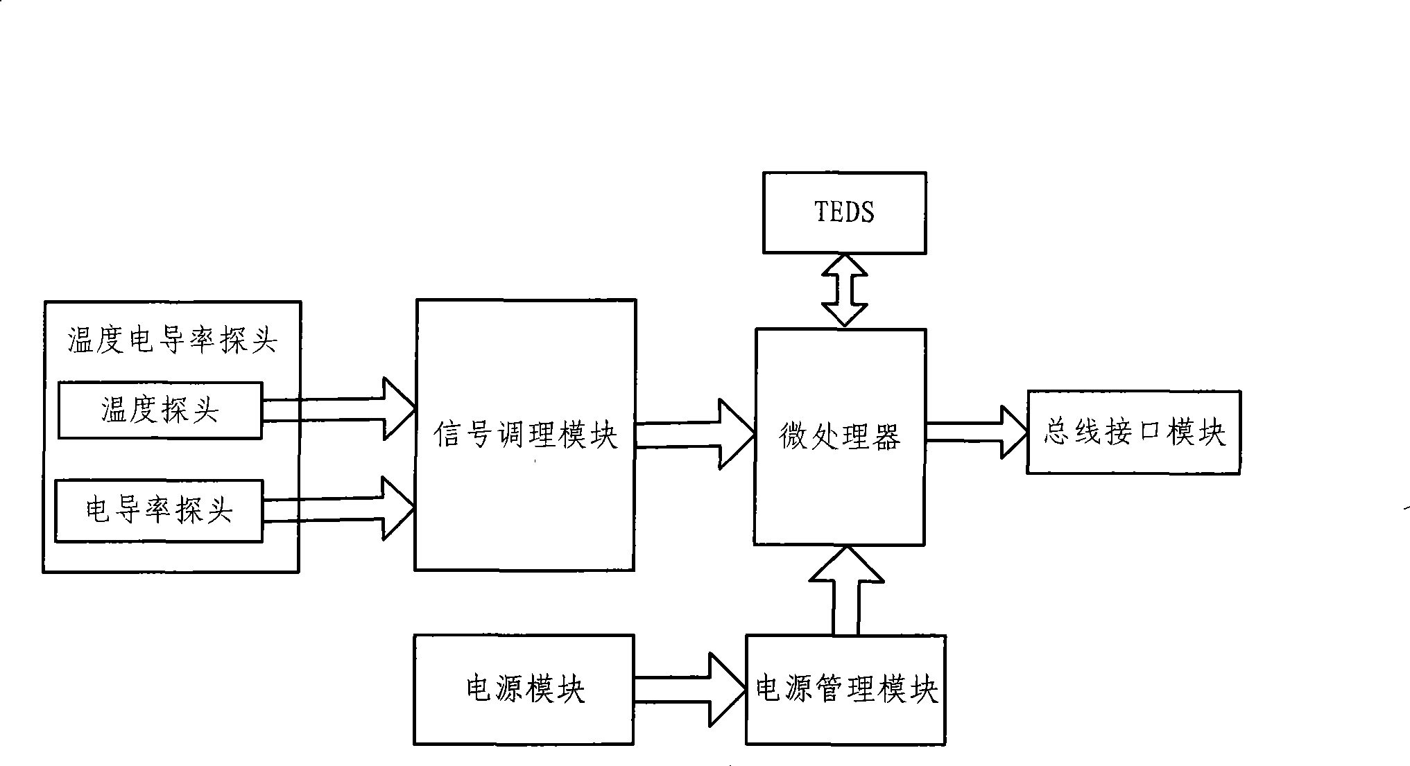
[0032] See figure 1 As shown, figure 1 It is the overall principle diagram of the hardware design of the water quality conductivity intelligent sensor of the present invention. In order to enhance the integration of the system, the microprocessor adopts the MSP 430 of American TI Company as the main control chip. Of course, other chips that can realize data processing and control can also be selected.

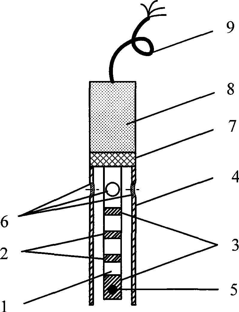
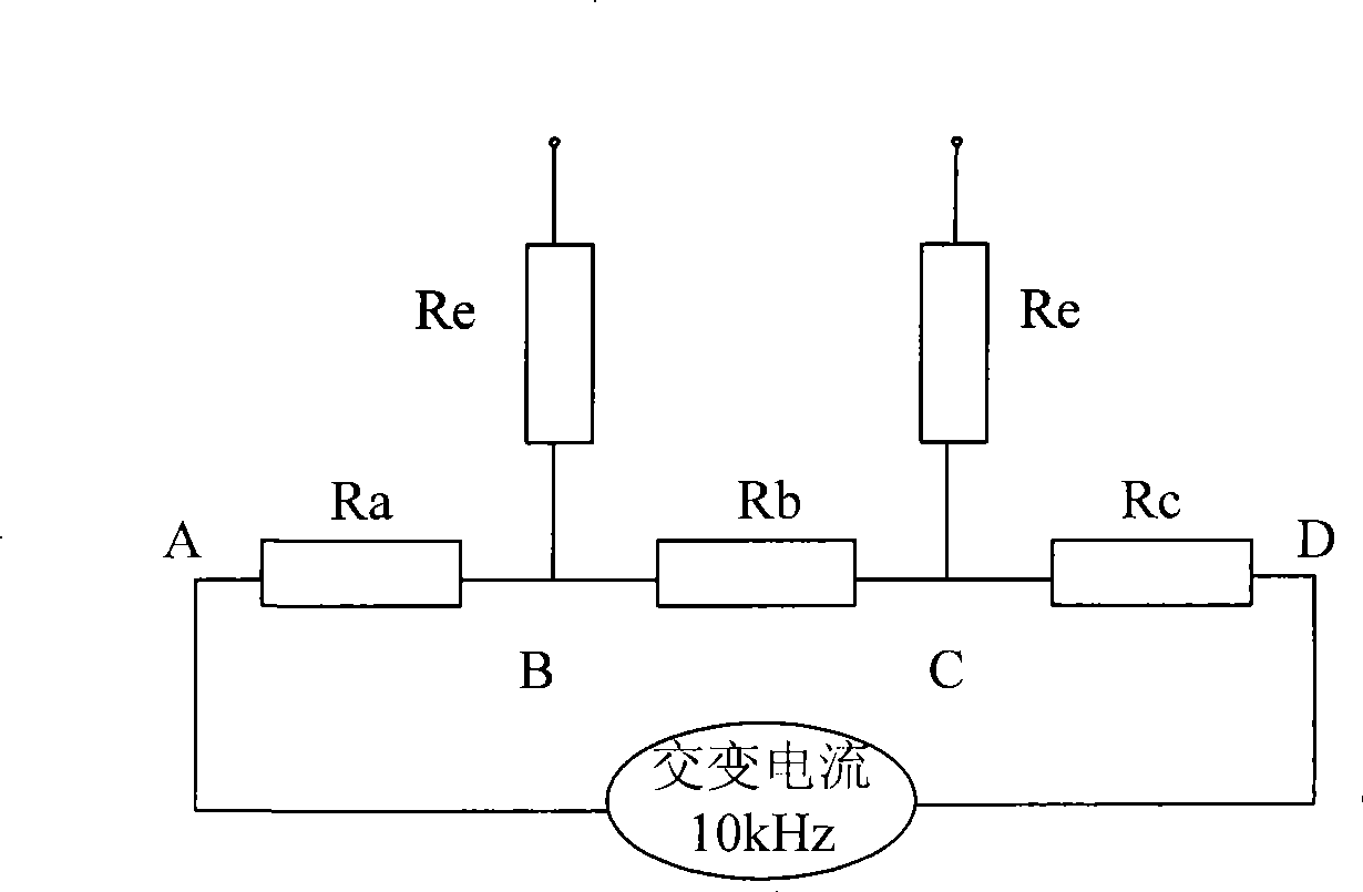
[0033] Among them, the sensitive part of the sensor is a temperature conductivity probe composed of a temperature probe and a conductivity probe connected into one body; the structure of the conductivity probe is as follows figure 2 As shown, it uses the current-voltage four-ring electrode method, including two...


PUM


Abstract

The invention discloses an intelligent sensor for the electrical conductivity of water quality. The sensor comprises a temperature-conductivity probe used for sensing the temperature and the electrical conductivity of the water; a signal conditioning module which is connected with the temperature-conductivity probe, forms a sensing circuit with the temperature-conductivity probe and carries out filtering and amplification to an output signal; a microprocessor which is connected with the signal conditioning module, is used for digitizing the signal input by the signal conditioning module and adopts IEEE1451 standards to carry out the calibration and alignment of channels; a bus interface module which is connected with the microprocessor and is used for the functions of networking and plugging and playing; and a power module which supplies power to the circuits of all parts of the sensor under the control of the microprocessor and realizes the characteristic of low power consumption. The invention can eliminate the polarization effect of the probe, has pollution resistance, large measuring range and low price, and is characterized by the functions of self alignment and compensation, self diagnosis and plugging and playing and high integrity.

Description

Technical field [0001] The invention relates to the field of water quality detection, in particular to a water quality conductivity intelligent sensor for detecting the conductivity of water bodies. Background technique [0002] The conductivity of water reflects the amount of inorganic acids, alkalis, and salts it contains, and is affected by temperature. This indicator is often used to estimate the total concentration of ions or salt content in water. Different types of water have different conductivity, so monitoring and controlling the water quality parameters that affect the normal progress of the water environment has great theoretical and practical significance. [0003] my country's water quality online automatic monitoring technology started late. At present, domestic electrode-type conductivity probes are generally two-electrode type. The disadvantage is that once the probe surface is contaminated, it will directly affect the measurement results. In water environment mo...

Claims


Application Information

Patent Timeline
IPC IPC(8): G01N27/416
Inventor 马道坤李道亮丁启胜王剑秦段青玲贺冬仙李飞飞
Owner CHINA AGRI UNIV
Learn More