
Rotary atomizer head type paining machine

A technology of rotary atomization and coating machine, which is applied in the direction of spraying device, electrostatic spraying device, spraying device with movable outlet, etc., which can solve the problems of poor coating quality, bending of rotating shaft, bearing damage, etc., and achieve improved coating quality. The effect of improving the quality of installation, improving reliability and improving productivity

Inactive Publication Date: 2009-03-25
ABB株式会社
View PDF1 Cites 4 Cited by
  • Summary
  • Abstract
  • Description
  • Claims
  • Application Information

AI Technical Summary

Problems solved by technology

[0012] In this way, if a radial load acts on the rotating shaft, there is a risk of damage to the turbine or bearing of the air motor or bending of the rotating shaft
In particular, in recent rotary atomizing head coating machines, since the rotary atomizing head is rotated at a high speed of 3,000 to 100,000 rpm, even a slight scratch or warp will have a bad influence on the coating quality

Method used


Image

  • Rotary atomizer head type paining machine
  • Rotary atomizer head type paining machine
  • Rotary atomizer head type paining machine

Examples


Embodiment Construction

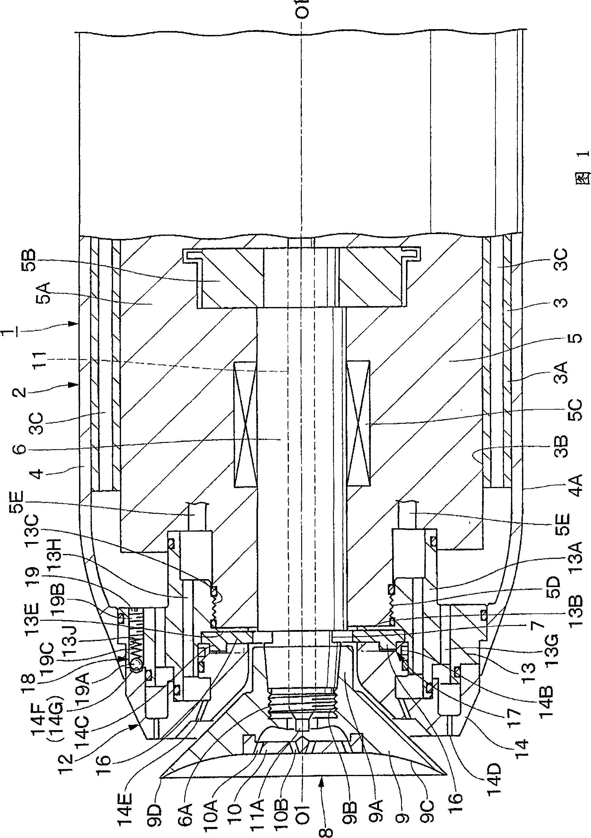
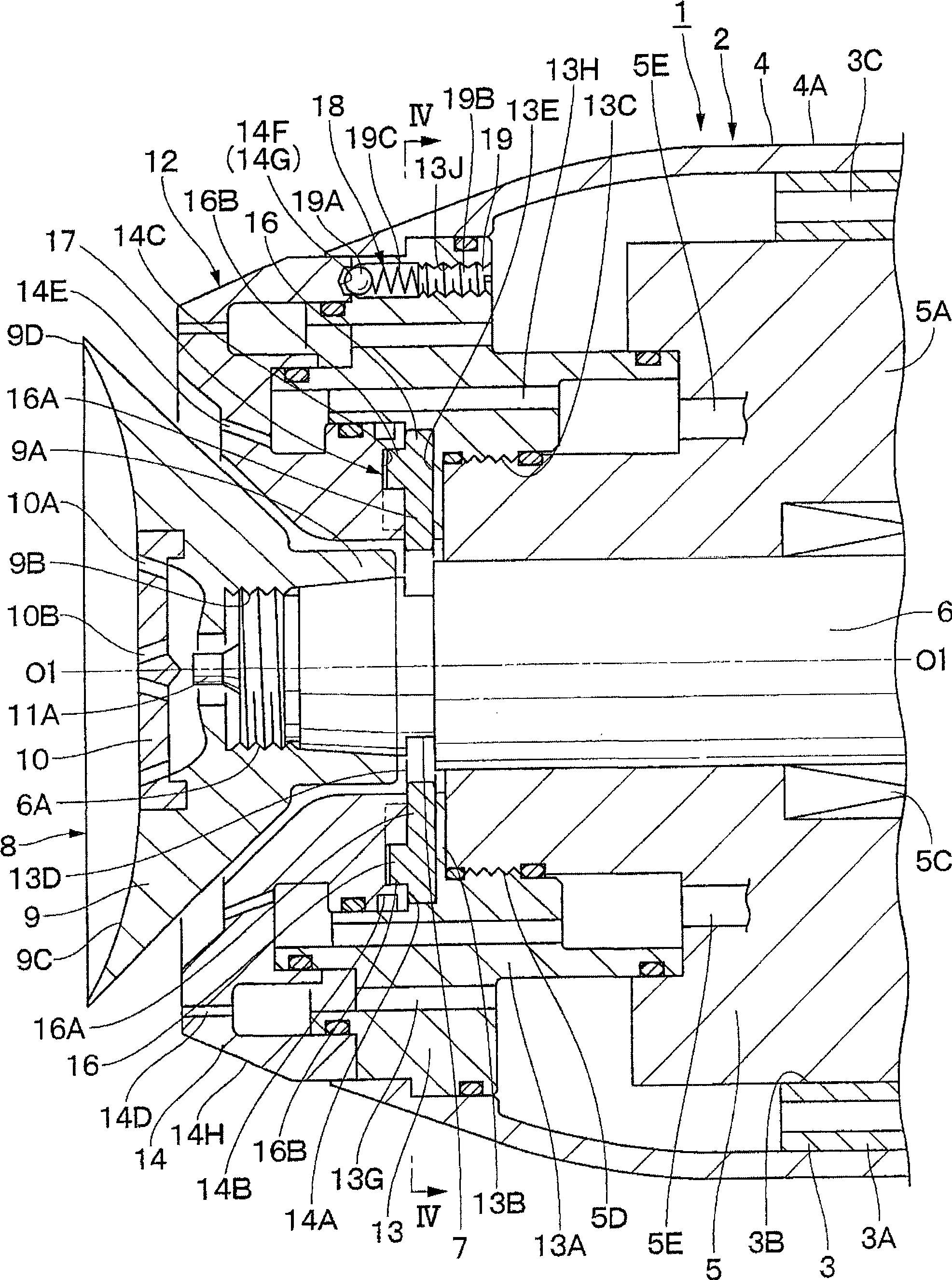
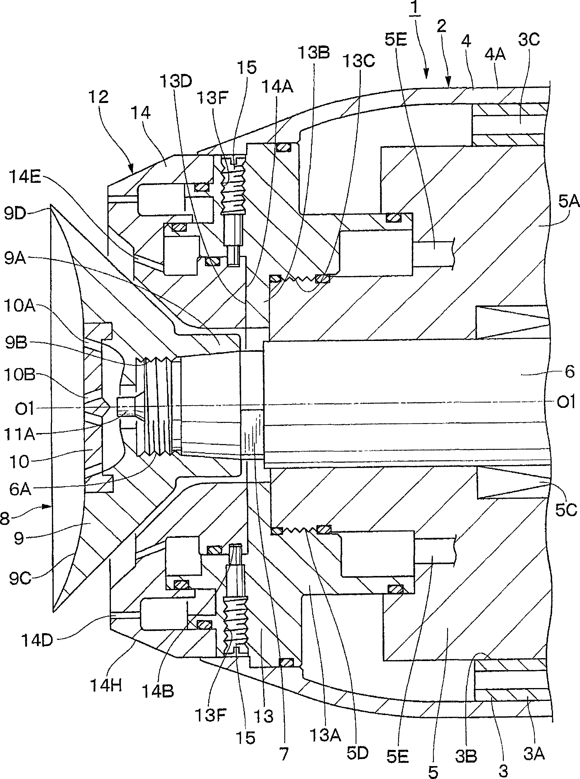
[0052] Hereinafter, a rotary atomizing head type coating machine according to an embodiment of the present invention will be described in detail with reference to the drawings.

[0053] First, Figure 1 to Figure 8 The first embodiment of the present invention is shown.

[0054] In FIG. 1 , reference numeral 1 denotes a rotary atomizing head type coating machine according to a first embodiment. This coating machine 1 is attached to the front-end|tip of the arm (not shown) of a robot for coating, a reciprocating mechanism, etc., for example. Moreover, the rotary atomizing head type coating machine 1 roughly includes a housing 2, an air motor 5, a rotating shaft 6, a fitting part 7, a rotary atomizing head 8, a feeding pipe 11, a shaping air ring 12, and the like which will be described later.

[0055] Reference numeral 2 is a casing forming the outer shape of the coating machine 1 . The case 2 is composed of a case main body 3 on the inside and a cover 4 on the outside. Her...


PUM


Abstract

Two engagement sections (7) are arranged on the outer peripheral side of a rotating shaft (6), a stationary ring (13) is attached forward of an air motor (5), a rotation ring (14) is rotatably provided on the stationary ring (13), and two slide plates (16) are arranged between the stationary ring (13) and the rotation ring (14) so as to be movable in the radial direction of the rotating shaft (6). A slider movement mechanism (17) is placed at the stationary ring (13) and the rotation ring (14), and the slider mechanism causes each slide plate (16) to be engaged with and separated from each engagement section (7) according to rotation of the rotation ring (14). When a worker simply holds the rotation ring (14) by one hand and rotates it, the slider movement mechanism (17) causes each slide plate (16) to engage with the engagement section (7) to fix the rotating shaft (6). In this state, a rotary atomizer head (8) can be rotated relative to the rotating shaft (6), which enables attachment and detachment of the atomizer head (8) to the rotating shaft (6).

Description

technical field [0001] The present invention relates to a rotary atomizing head type coating machine suitable for coating, for example, automobile bodies, furniture, electric products and the like. Background technique [0002] Generally, when painting automobile bodies, furniture, electrical appliances, etc., a rotary atomizing head type coating machine with good coating efficiency and coating quality is used for coating. This rotary atomizing head type coating machine has, for example: a cylindrical housing mounted on the front end of an arm of a coating robot, an air motor accommodated in the housing and rotating a rotating shaft at high speed, and a motor located in the housing. A bell-shaped or cup-shaped rotary atomizing head attached to the front end of the rotary shaft, and a paint passage for passing the paint supplied to the rotary atomizing head. [0003] Furthermore, the rotary atomizing head type coating machine uses an air motor to rotate the rotary atomizing ...

Claims


Application Information

Patent Timeline
Patent Type & Authority Applications(China)
IPC IPC(8): B05B5/04B05B3/10
CPCB05B3/1064B05B3/1035B05B3/1014B05B3/1042B05B3/1092B05B5/04B05B3/10
Inventor 安田真一松浦利文
Owner ABB株式会社
Learn More