
Electrical refrigerator

A technology for refrigerators and refrigerators, which is applied to household refrigerators, coolers, lighting and heating equipment, etc., to achieve the effect of improving drive reliability

Active Publication Date: 2009-03-11
HITACHI APPLIANCES INC
View PDF1 Cites 35 Cited by
  • Summary
  • Abstract
  • Description
  • Claims
  • Application Information

AI Technical Summary

Problems solved by technology

Furthermore, there is a so-called lock in which the water droplets freeze and the blower does not operate.

Method used


Image

  • Electrical refrigerator
  • Electrical refrigerator
  • Electrical refrigerator

Examples


Embodiment Construction

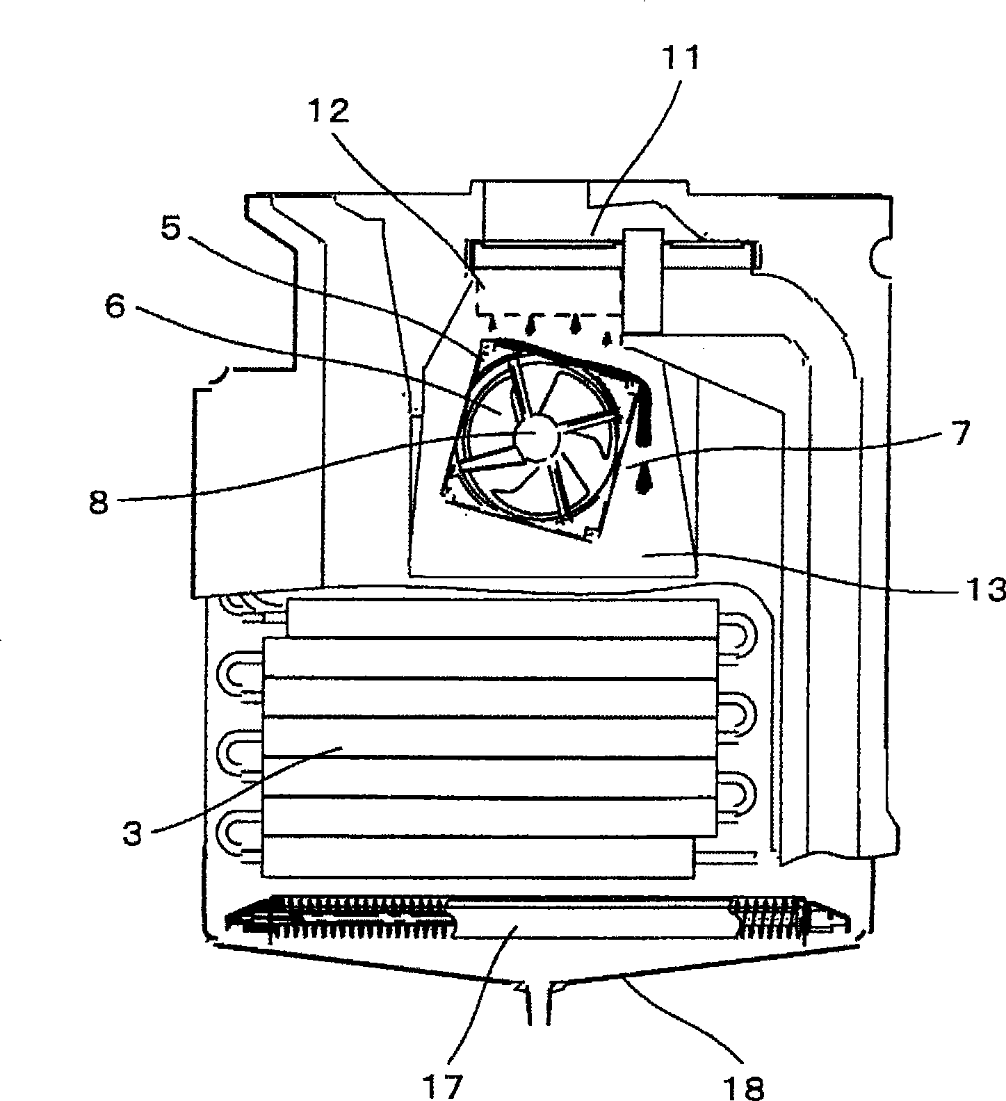
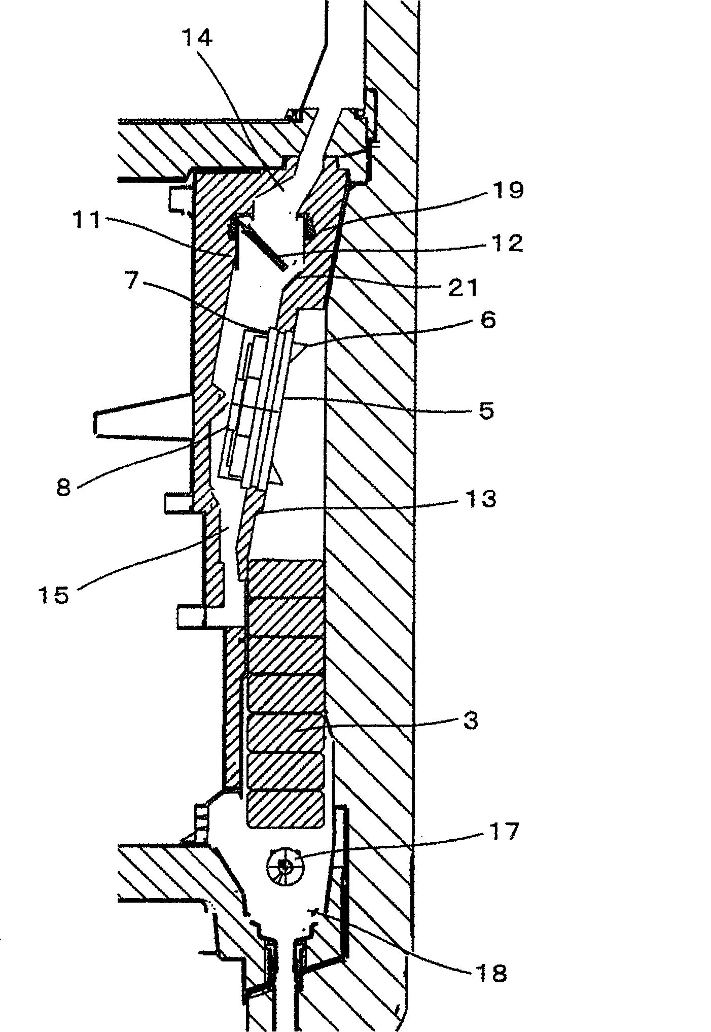
[0022] Below, refer to Figure 1 ~ Figure 3 Embodiments of the refrigerator of the present invention will be described. figure 1 It is a cross-sectional view of a main part of the refrigerator according to the embodiment of the present invention. figure 2 It is an installation front view of the air blower and damper of this embodiment. image 3 It is an installation sectional view of the air blower and damper of this embodiment.

[0023] Such as figure 1 As shown, 1 is the main body of the refrigerator, 2 is the refrigerator compartment arranged on the top of the refrigerator main body 1, 20 is the vegetable compartment arranged at the bottom of the refrigerator main body 1, and 10 is arranged between the refrigerator compartment 2 and the vegetable compartment 20 freezer. On the rear side of the freezer compartment 10, a heat exchanger 3 for cooling cold air in the refrigerator is arranged. There are cold air ducts 14, 15 for cold air circulation around the heat excha...


PUM


Abstract

The invention provides a refrigerator improving driving reliability of blower. The refrigerator of the invention comprises a refrigerating chamber provided at the upper part of the refrigerator body, a freezing chamber provided at the lower part of the refrigerator body, a blower conveying cooling air to the refrigerator, a cooling air duct located at the upper part of the freezing chamber and provided with the blower, an air door located at the upper part of the blower for adjusting the supplying of the cooling air conveyed by the blower to the refrigerator, a baffle for rotatably providing the air door in the cooling air duct and controlling the cooling air passing in the cooling air duct; the blower comprises a fan and a fan cover provided around the fan and the blower is provided having tilt from upper part if the fan cover to the left and right directions viewing from the face of the refrigerator body; the cooling air duct has a tilt part at the upper part of the fan; the baffle rotates until the end of the baffle locating at the upper part of the tilt part.

Description

technical field [0001] The present invention relates to refrigerators. Background technique [0002] For a long time, the air blower of the refrigerator has adopted the axial flow type for the sake of small size and power saving. As a conventional structure, there exists the technique described in patent document 1 - Japanese Unexamined Patent Publication No. 2002-130188. Figure 4 It is a cross-sectional view of a main part of a refrigerator equipped with a conventional air blower and cooling equipment. Figure 5 It is the perspective front view of the main part of the refrigerator equipped with the conventional blower and cooling equipment. Figure 6 It is a front view of an air blower used in a conventional refrigerator. [0003] exist Figure 4 Among them, 1 is a main body of the refrigerator, 2 is a refrigerator compartment, and a heat exchanger 3 is arranged on the back side of the refrigerator compartment 2 . In addition, a refrigerator inner duct 4 forming an air ...

Claims


Application Information

Patent Timeline
IPC IPC(8): F25D11/02F25D17/08F25D21/08
Inventor 荒川展昭笹村和文茂中启介
Owner HITACHI APPLIANCES INC
Learn More