
Battery assembly

A battery and component technology, applied in the field of battery components, can solve the problems of accumulation, condensation of cooling air, difficult short circuit, etc., and achieve the effect of compact overall structure, reducing vehicle space and avoiding short circuit

Active Publication Date: 2009-03-04
TOYODA GOSEI CO LTD
View PDF1 Cites 45 Cited by
  • Summary
  • Abstract
  • Description
  • Claims
  • Application Information

AI Technical Summary

Problems solved by technology

[0006] However, the conventional battery pack proposed in Japanese Unexamined Patent Publication No. 2001-313,018 has a problem in that the unit cells arranged near the middle are not easily dissipated compared with the unit cells arranged near the opposite ends. heat
[0011] However, in the conventional battery pack proposed in Japanese Unexamined Patent Publication No. 2006-48,996, there may be a case where foreign matter such as dust accumulates in the space 104 of the battery sub-assembly
In this case, it is difficult to cool the unit cells 100 uniformly, so that a difference occurs among the cooling characteristics of the unit cells 100 .
In addition, although air from an air conditioner is generally used as a cooling medium, the cooling air may condense in the space 104 due to the temperature difference between the cooling air and the outside air
If the formed dew drops move to the electrodes of the unit cells 100, needless to say, it is difficult for this conventional storage battery assembly to avoid short circuits.

Method used


Image

  • Battery assembly
  • Battery assembly
  • Battery assembly

Examples


Embodiment

[0043] Hereinafter, the battery module of the present invention will be described in detail with reference to specific examples and experimental examples.

no. 1 example

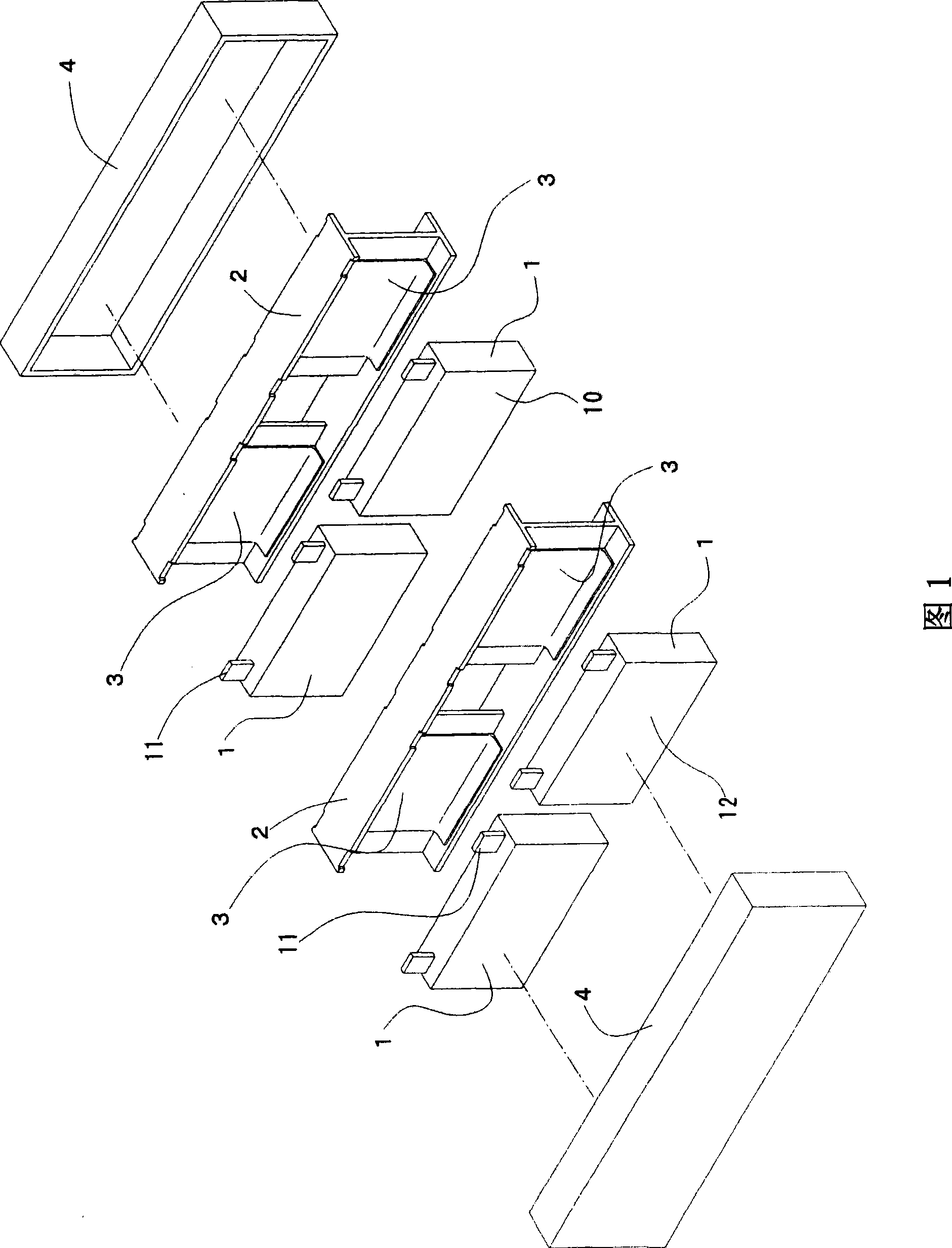
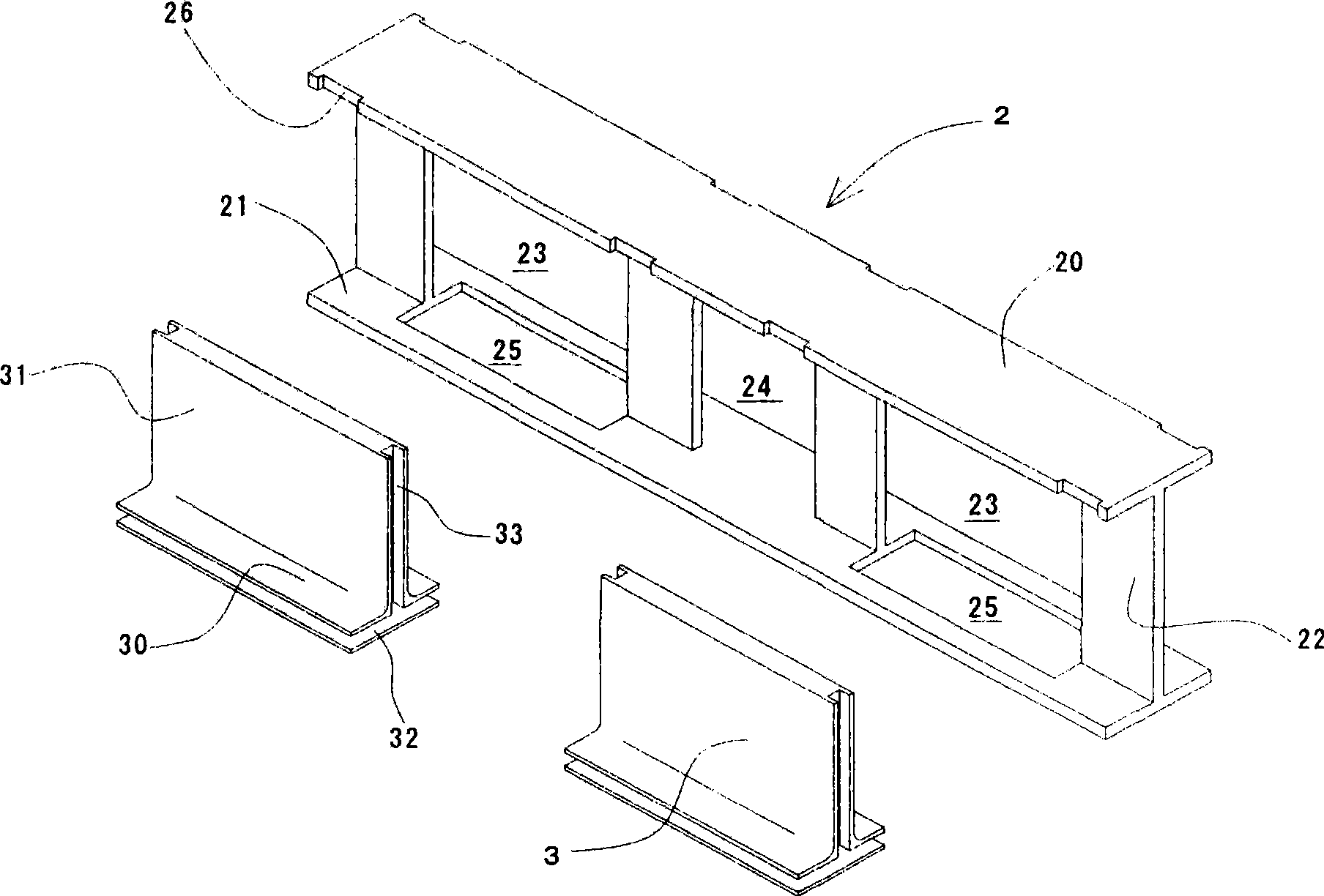
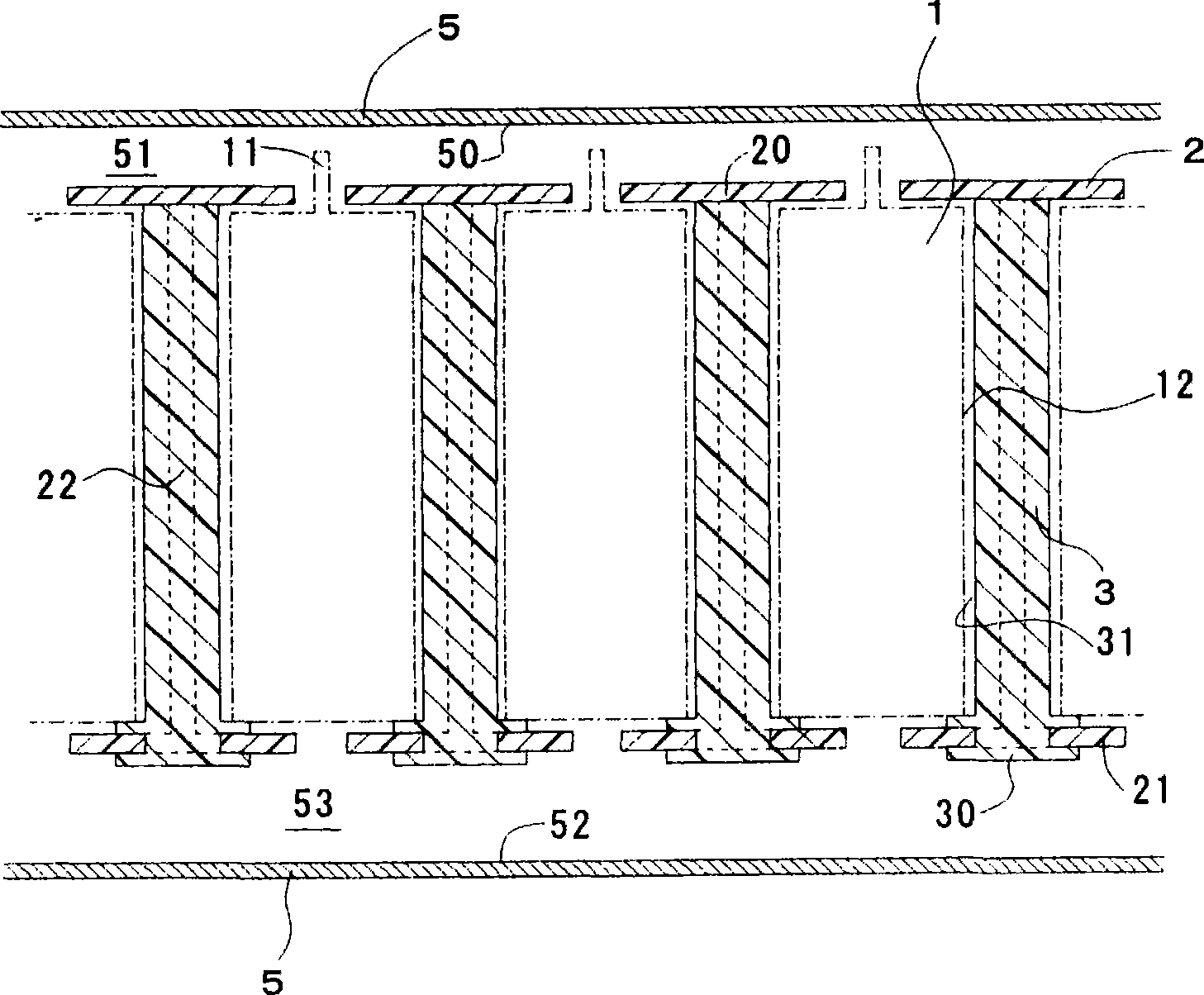
[0044] Fig. 1 is an exploded isometric view illustrating a battery assembly according to a first embodiment of the present invention. The battery assembly according to the first embodiment includes dozens of unit cells 1, separators 2 and heat conducting members 3. The single cell 1 is formed in a rectangular parallelepiped structure, and each has two sides 12 with the largest area. The separator 2 is made of electrically insulating resin. Half of the single cells 1 and the heat-conducting parts 3 are arranged alternately in rows, thereby forming the left battery sub-assembly in the figure. The other half of the single cells 1 and the heat-conducting elements 3 are also arranged alternately in rows to form the right battery sub-assembly in the figure. The formed two rows of battery sub-assemblies—the left and right battery sub-assemblies are arranged parallel to each other. Note that in the two rows of battery subassemblies arranged in parallel with each other, the separator 2 is ...

no. 2 example

[0056] Such as Figure 4 As shown, the battery assembly according to the second embodiment of the present invention includes a heat-conducting member 3 provided with a lug 34 that extends downward from the base 30 into the space 53. Except for this feature, the battery assembly according to the second embodiment is constructed in the same manner as the battery assembly according to the first embodiment.

[0057] The battery assembly according to the second embodiment of the present invention includes a lug 34, which makes the surface area of ​​the base 30 of the heat-conducting member 3 exposed in the space 53 larger. Therefore, the cooling efficiency of the battery assembly according to the second embodiment of the present invention is higher than that of the battery assembly according to the first embodiment of the present invention.


PUM

PropertyMeasurementUnit
thermal conductivityaaaaaaaaaa

Abstract

A battery assembly includes single-battery cells, and thermally-conductive members. The thermally-conductive members are formed of a soft material as a plated configuration. The soft material exhibits thermal conductivity and electric insulatability. The single-battery cells, and the thermally-conductive members are adhered to each other, and are disposed one after another alternately in a row, thereby interposing the thermally-conducive members between the single-cell batteries. The thermally-conductive members include a radiation surface respectively from which heat that the single-battery cells produce radiates. The single-battery cells are cooled indirectly by cooling the radiation surfaces of the thermally-conductive members.

Description

Technical field [0001] The invention relates to a battery assembly, which is suitable for use as a power source for electric vehicles and hybrid vehicles. Background technique [0002] Nickel-hydrogen secondary batteries and lithium-ion batteries can be used as driving power sources for electric vehicles, they need to have a high energy density, and they need to occupy as little vehicle space as possible. Accordingly, it is common practice to construct a battery assembly by assembling a plurality of single cells (single battery cells). For example, the single battery is formed into a rectangular parallelepiped structure, and its battery capacity ranges from several volts to several tens of volts. Dozens of single batteries are connected in series, and then the formed battery sub-assembly is housed in a casing to form Battery components. The formed battery assembly is installed, for example, under the rear passenger seat of the vehicle or in the luggage compartment of the vehicle....

Claims


Application Information

Patent Timeline
Patent Type & Authority Applications(China)
IPC IPC(8): H01M10/50H01M10/60H01M10/613H01M10/617H01M10/625H01M10/6551H01M10/6555H01M10/6556H01M10/663H01M50/209H01M50/291
CPCH01M10/5004H01M10/5057H01M10/5046H01M10/5059H01M10/5055H01M10/5016H01M10/5032H01M2/1077H01M10/5053H01M10/625H01M10/647H01M10/6556H01M10/6551H01M10/6557H01M10/6555H01M10/6554H01M10/613Y02E60/10H01M50/209H01M50/291
Inventor 内田安则椿公男竹尾茂树大中博史铃木达雄三井研一
Owner TOYODA GOSEI CO LTD
Learn More