
Pressure accumulation water supply system

A water supply system and pressure storage technology, which is applied in the directions of water supply equipment, water supply pool configuration, energy industry, etc., can solve the problems of insufficient and effective utilization of renewable energy, difficulty in meeting the requirements of water supply pressure, and poor working conditions, etc. To achieve the effect of convenient installation, water saving and low cost

Inactive Publication Date: 2009-02-18
陈鸣
View PDF0 Cites 6 Cited by
  • Summary
  • Abstract
  • Description
  • Claims
  • Application Information

AI Technical Summary

Problems solved by technology

In cities, automatic high-rise water supply equipment is usually used to supply water to high-rise buildings. The characteristic is to supply water to a concentrated area, which is a secondary pressurized water supply. The equipment cost is high and the operating cost is high.
However, in rural areas and mountainous areas, most of the residents live scatteredly, and supplying water to a scattered area cannot copy the water supply mode of the city.
If a water pump is used for water supply, the lifting height of the water supply is limited due to the use of atmospheric pressure, coupled with the loss along the pipeline and the local loss of pipeline components, the pressure of the water supply is difficult to meet the requirements; and the water pump must be turned on when the water is used, and when it is not in use Turning off the water pump cannot make full and effective use of renewable energy, such as solar energy, wind energy, etc.; the working conditions of the water pump are relatively limited, and the working conditions are poor, and the load is affected

Method used


Image

  • Pressure accumulation water supply system
  • Pressure accumulation water supply system
  • Pressure accumulation water supply system

Examples


Embodiment Construction

[0023] Referring to the accompanying drawings, through the description of the embodiments, the specific implementation of the present invention, such as the shape, structure, mutual position and connection relationship between the various parts, the function and working principle of each part, and the manufacturing process And the method of operation and use, etc., are described in further detail to help those skilled in the art have a more complete, accurate and in-depth understanding of the inventive concept and technical solution of the present invention.

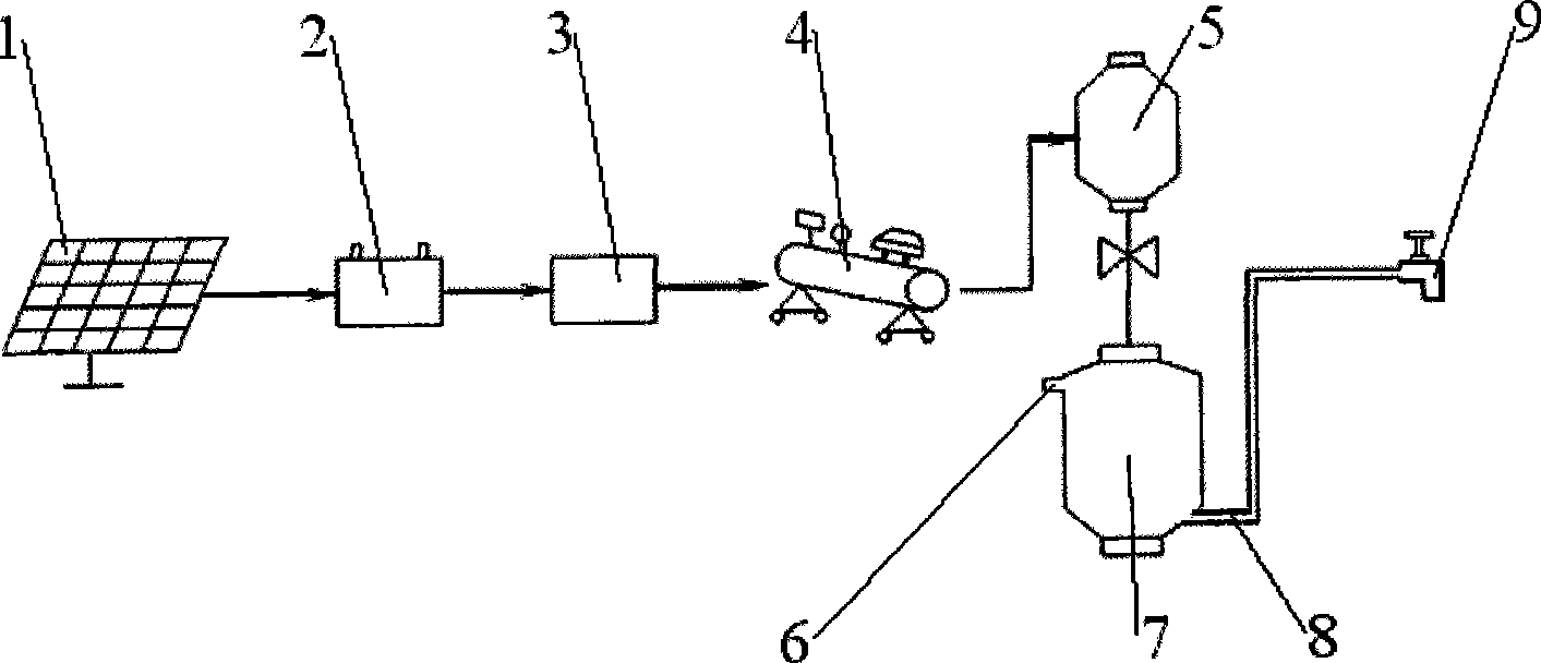
[0024] Such as figure 1 , figure 2 The structure of the present invention expressed, the present invention is a pressure storage water supply system, including a water storage tank, a user terminal 9, and a water inlet 6 and a water outlet 8 are arranged on the body of the water storage tank.

[0025] In order to solve the problems existing in the current known technology described in the background technology section ...


PUM


Abstract

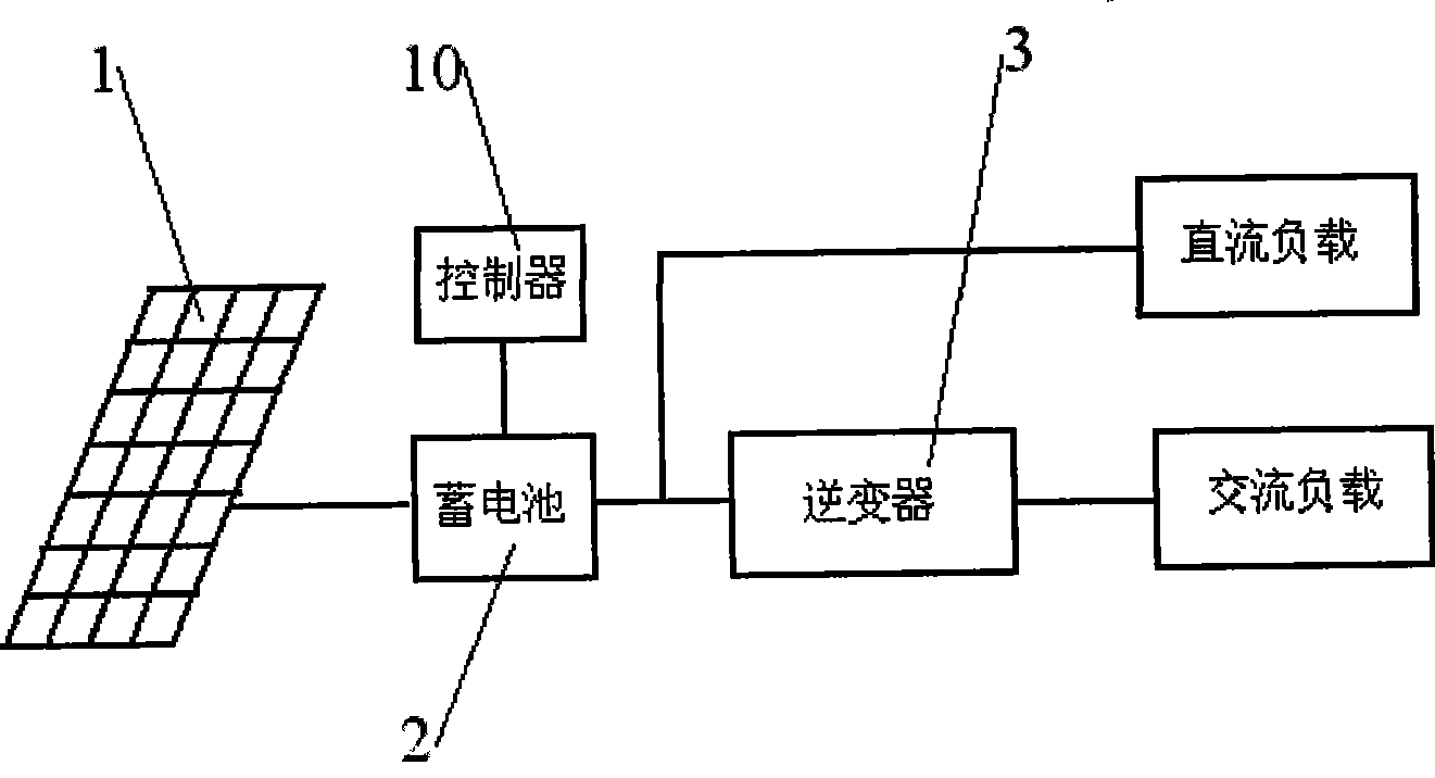
The invention discloses a pressure storing water supply system. The water storage tank is a pressurized water storage tank(7) and the tank body is a pressure-proof sealed structure. The water supply device is further provided with an air compressor(4) and a pressure tank(5) whose tank body is also a pressure-proof sealed structure. The air compressor(4) supplies compressed air to the pressure tank(5). The pressure tank(5)is communicated with the pipeline of the pressurized water storage tank(7). Adopting above technical proposal, the pressure storing water supply system reduces the cost on water supply equipment and operation cost and saves water cost. The pressure storing water supply system is lower in fabrication cost and is convenient to install. Meanwhile, a solar cell generates electricity which is supplied to the water supply system to store pressure; therefore, using green energy, the pressure storing water supply system causes no pollution to the environment. The pressure storing water supply system suits the development of modernized new countryside and accords with national industry policy and the policy on benefit to the people.

Description

technical field [0001] The invention relates to the water supply system technology of domestic water, in particular, the invention relates to a pressure storage water supply system suitable for rural or mountainous areas. Background technique [0002] At present, the drinking water project for the rural population is being implemented in an all-round way. Local conditions and key points are highlighted to ensure that the project will be built in one place and completed in one place, so as to solve the drinking water safety problem of hundreds of millions of farmers. [0003] However, during the implementation of the project, a new problem emerged, that is, due to the scattered living of rural residents, the long water supply pipelines, and the inability to centralize water supply, the pressurization of water supply requires electricity and the operation of water supply costs, so the cost of water supply The cost is still relatively high. The income of rural or mountainous r...

Claims


Application Information

Patent Timeline
IPC IPC(8): E03B11/02E03B5/00H02J7/32
CPCY02P80/10
Inventor 陈鸣
Owner 陈鸣
Learn More