Camera array calibration method based on matrix decomposition

A technology of matrix decomposition and calibration method, which is applied in the field of camera array calibration, and can solve the problems of huge camera array, scattered distribution of cameras, and difference of vision of cameras.

Inactive Publication Date: 2009-02-11
ZHEJIANG UNIV
View PDF0 Cites 23 Cited by
  • Summary
  • Abstract
  • Description
  • Claims
  • Application Information

AI Technical Summary

Problems solved by technology

[0010] The purpose of the present invention is to overcome the deficiencies of the existing calibration technology, fully solve the situation that the camera array is relatively large, or the distribution of the cameras is relatively scattered, and the camera field of view is greatly different, and provides a camera array calibration method based on matrix decomposition

Method used


Image

  • Camera array calibration method based on matrix decomposition
  • Camera array calibration method based on matrix decomposition
  • Camera array calibration method based on matrix decomposition

Examples


Embodiment Construction

[0106] Below in conjunction with embodiment further illustrate the present invention.

[0107] A camera array calibration method based on matrix decomposition, comprising the following steps:

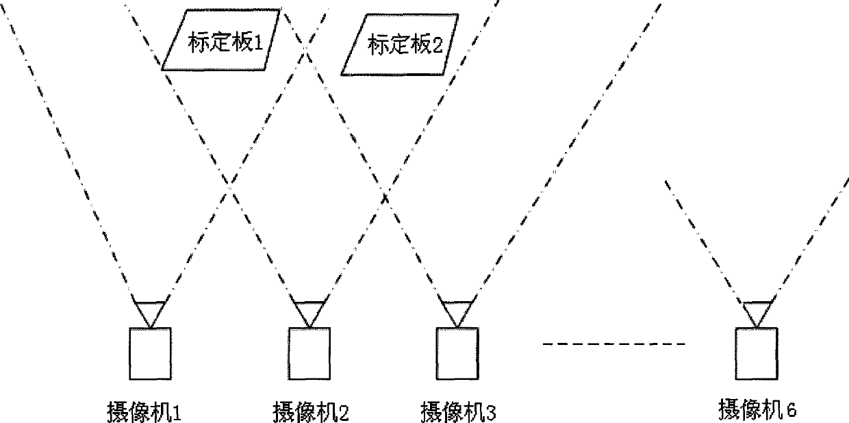
[0108] 1. Suppose there are six cameras taking photos of the calibration board at 24 different positions (such as figure 1 shown), and at the same time, the obtained images are also taken in accordance with the sequence of photographing and the corresponding camera number;

[0109] In the following representations, we will use the subscript i to indicate the camera number, and the superscript j to indicate the number of the calibration plate image. At the same time, each camera captures at least 4 images of the calibration plate.

[0110] 2. Use the actual physical coordinate data of the feature points on the calibration board and the image data obtained by taking pictures to obtain the homography matrix of the camera

[0111] a) The imaging model of the camera is as formula (1)

...


PUM


Abstract

The invention discloses a camera array calibration method based on matrix decomposition, which comprises the following steps of 1) numbering a camera and taking photos of a calibration plate, and also numbering the obtained images according to the taking-photo sequence and the corresponding camera; 2) calculating homographic matrix of the camera by using the actual physic coordinate data of characteristics points on the calibration plate and the image data obtained from taking the photos; 3) constructing and measuring the matrix by using the calculated homographic matrix, the corresponding camera and the number of the calibration plate, and adjusting a proportional factor of the homographic matrix; 4) choosing a corresponding method to conduct matrix decomposition to measurement matrix W with data gap according to the arrangement condition of the camera array minus concentration or sparsity; 5) adding measurement restriction and calculating the internal and the external parameters of the camera; 6) conducting nonlinear optimization to the obtained data. The invention is suitable for camera array arranged in any way and can exactly obtain the internal and the external parameters of the camera.

Description

technical field [0001] The invention belongs to the field of computer multimedia technology, in particular to stereo vision, camera array calibration technology in 3DTV (three-dimensional television) and IBR (image-based rendering technology). Background technique [0002] Camera calibration is the process of obtaining the imaging geometric model of the camera, and the parameters of the geometric model are the camera parameters. These include the camera's internal geometrical optics parameters (intrinsic parameters) A i And the positional relationship (external parameters) of the camera relative to the world coordinate system, including the rotation matrix R i and translation vector t i . where A i The form is as follows: [0003] A i = α i c i ...

Claims


Application Information

Patent Timeline
IPC IPC(8): H04N13/00H04N17/00G06T7/00G06T7/80
Inventor 张超李东晓张明张文娜冯雅美谢贤海席明杨青青
Owner ZHEJIANG UNIV
Why Eureka
Try Eureka