
Contact tip construction of non-excited tapping switch

A technology of tap changer and contact, which is applied in the direction of electric switch, electrical components, prior contact arrangements, etc. It can solve the problems of application limitation of contact structure, increase of running stroke, poor stability, etc., and achieve switch gear shifting operation torque light effect

Active Publication Date: 2009-02-11
WUHAN TAIPU TRANSFORMER CHANGER
View PDF0 Cites 10 Cited by
  • Summary
  • Abstract
  • Description
  • Claims
  • Application Information

AI Technical Summary

Problems solved by technology

However, the operating torque of the contact structure mainly depends on the length between two adjacent static contacts, the diameter of the annular moving contact and the pressure of the spring. The shorter the chord length or the larger the diameter of the annular moving contact, the greater the operating torque. The smaller the pressure is, the pressure is designed according to the current of a single contact, and the change is limited. The length of the center chord is restricted by the insulation level between two adjacent static contacts. If the diameter of the moving contact is too large, the stability will be poor and it will be easily skewed. At the same time, it will affect The distance between it and other non-contact static contacts leads to a decrease in the insulation level, so when the switching current is large, the number of annular moving contacts is large; when the insulation level between the static contacts is high, the chord length increases to make the moving contacts Cutting too deep between the static contacts will increase the operating stroke when shifting gears, causing the switch torque to increase or even fail to rotate, especially for switches with high current and multi-phase combination, it is more difficult when the insulation level between the static contacts is high. implementation, so that the application of this contact structure is limited

Method used


Image

  • Contact tip construction of non-excited tapping switch
  • Contact tip construction of non-excited tapping switch
  • Contact tip construction of non-excited tapping switch

Examples


Embodiment Construction

[0015] Embodiments of the present invention are further described below in conjunction with the accompanying drawings:

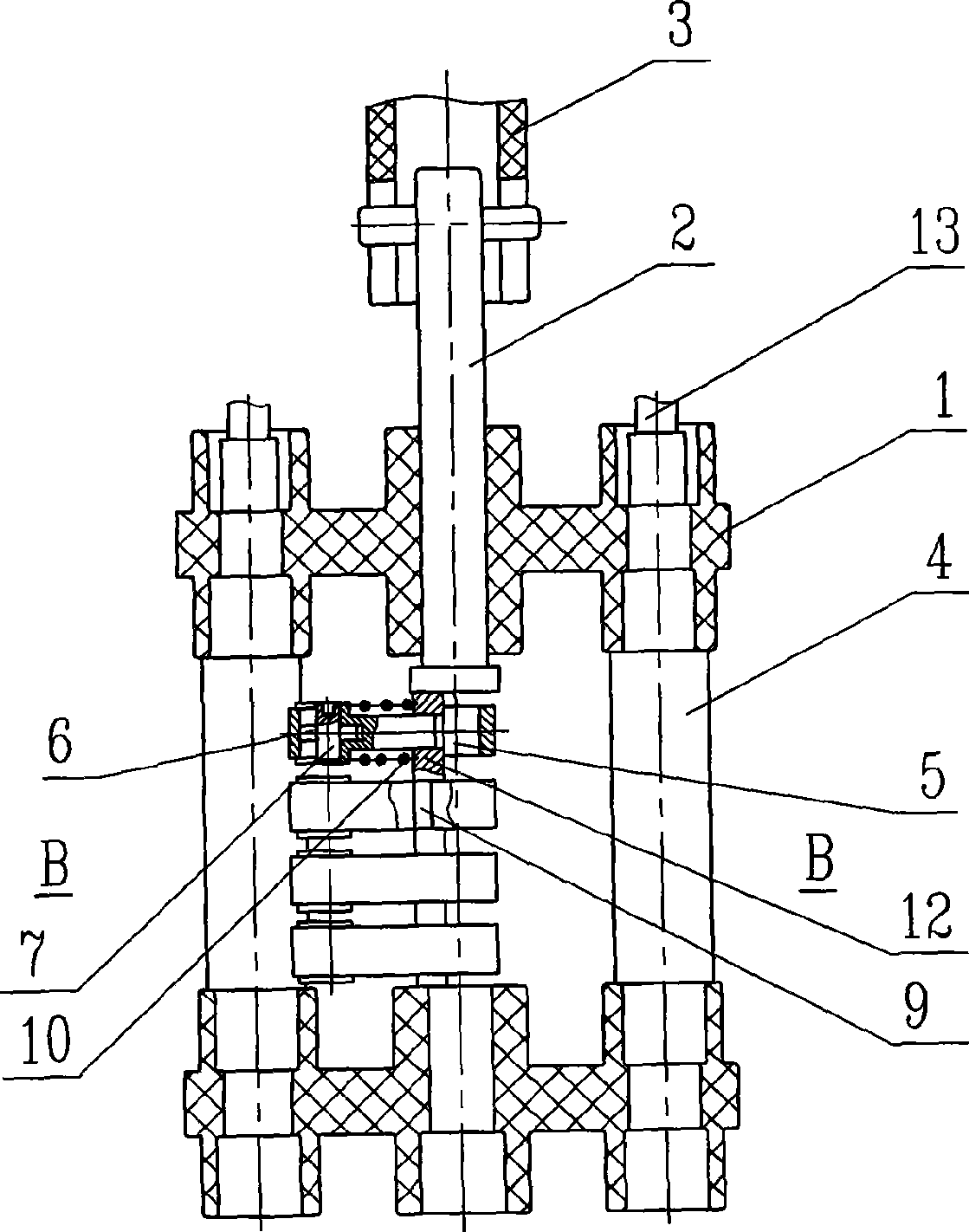
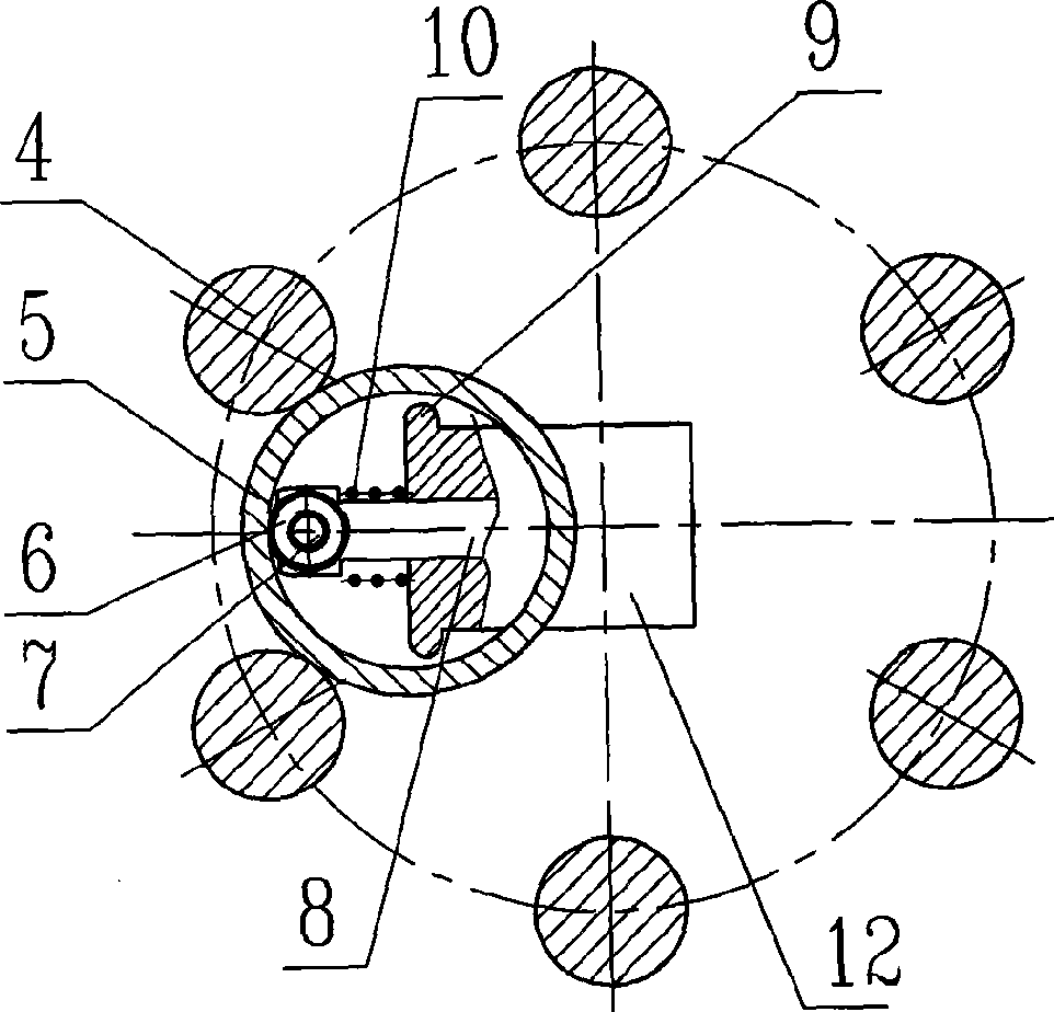
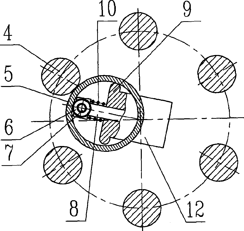
[0016] An example of the present invention is figure 1 , 2 . As shown in 3, it is a single-phase five-speed non-excitation drum-shaped tap changer, including switch supports 1 arranged up and down, and a main shaft 2 is installed between the two switch supports, and the upper end of the main shaft is connected with the switch operating mechanism 3 , an eccentric support piece 12 is installed on the main shaft, and a columnar fixed contact 4 is arranged at intervals along the circumferential direction between the two switch supports. The upper end of the columnar fixed contact is connected with a lead wire 13 or a terminal, and two adjacent columnar fixed contacts There is a ring-shaped moving contact 5 across the head, and the ring-shaped moving contact is set on the support and configured with the radial sliding pin 8 and the spring 10 installed on the sup...


PUM


Abstract

The invention relates to a contact structure of an excitation-free tapping switch used for a transformer. The contact structure comprises an upper switch support, a lower switch support, a main shaft arranged between the two switch supports, a supporter arranged on the main shaft, columnar fixed contacts alternately arranged between the two switch supports along the circumferential direction, and ring-shaped moving contacts which are arranged between each two adjacent fixed contacts and sheathed on the supporter and matches with a radial sliding pin and a spring that are arranged on the supporter. The contact structure is characterized in that a lateral shifter is arranged on each side of the supporter corresponding to the pores of the ring-shaped moving contacts. When the switch is shifted, the ring-shaped moving contacts are pushed to rotate to a predetermined direction by a rotation moment formed under the combined action of the external fixed contacts and the internal lateral shifters, such push can reduce the rotation moment during operating the contact to shift the switch, so as to easily complete the tap changing of the switch, and such effect is especially distinct when the number of the switch moving contacts is large or the chord length among the fixed contacts is increased.

Description

technical field [0001] The invention relates to a contact structure of an off-excitation tap changer for a transformer. Background technique [0002] The existing off-excitation tap changer contacts include a fixed contact and a moving contact that bridges between two adjacent fixed contacts. The ring moving contact is in reliable contact with the fixed contact under the spring force. When shifting gears, under the action of the torque of the main shaft and the supporting member, the annular moving contact overcomes the pressure of the spring and runs along the surface of the columnar static contact from one side to the other side of the fixed contact to complete the gear shifting process. The ring-shaped moving contact has the characteristics of simple structure, strong operation feel, precise positioning and the like. However, the operating torque of the contact structure mainly depends on the length between two adjacent static contacts, the diameter of the annular movin...

Claims


Application Information

Patent Timeline
IPC IPC(8): H01H1/56H01H19/12H01H21/20
Inventor 许志江
Owner WUHAN TAIPU TRANSFORMER CHANGER
Learn More