
Vehicle steering handle structure

A technology for handlebars and vehicles, which is applied to steering mechanisms, bicycle accessories, transportation and packaging, and can solve problems such as inability to reduce weight

Inactive Publication Date: 2012-08-22
KYMCO
View PDF3 Cites 0 Cited by
  • Summary
  • Abstract
  • Description
  • Claims
  • Application Information

AI Technical Summary

Problems solved by technology

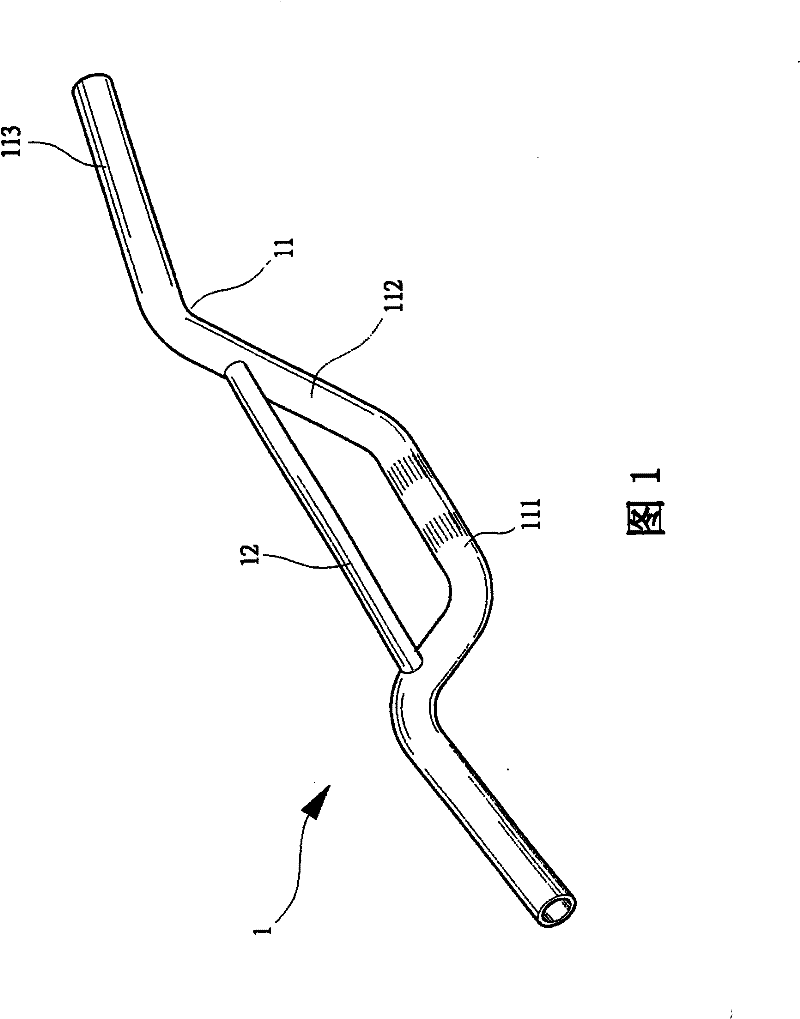
The structure of the above-mentioned conventional steering handle 1 can certainly make the steering handle 1 have stronger rigidity through the setting of the auxiliary pipe 12, but it cannot be lightweight because the steering handle 1 has the auxiliary pipe 12. There is a need for improvement

Method used


Image

  • Vehicle steering handle structure
  • Vehicle steering handle structure
  • Vehicle steering handle structure

Examples


Embodiment Construction

[0011] In order to make it easier to understand the structure of the present invention and the effects that can be achieved, it is described as follows in conjunction with the drawings:

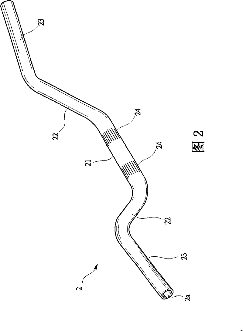
[0012] First, see figure 2 As shown, the steering handle 2 of the present invention is composed of a hollow body tube 2a. The body tube 2a is recessed in the middle to form a connecting portion 21, and the two ends of the connecting portion 21 extend obliquely upward to form a rising part 22, and at the end of the rising part 22, a section of gripping part 23 is extended in a substantially horizontal direction. In addition, a joint area 24 with two intervals and a rough surface is provided near the center of the connecting part 21. .

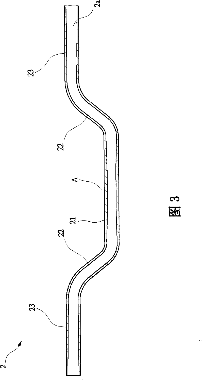
[0013] please cooperate image 3 , 4 For reference, since the steering handle 2 is left-right symmetrical with the center line A, the structure of the tubular body 2a will be described with one side below. The steering handle 2 of the present invention main...


PUM


Abstract

The invention relates to a vehicle steering handle structure, which is composed of a ducted body tube. A connecting part is concavely arranged at the middle part of the tube, raising parts are formed by extending upwards and slanchways from the both ends of the connecting part, a holding part is also formed by extending in the slightly horizontal direction from the end of the raising part, and a bonding zone between two coarse surfaces is also arranged on the connecting part. The vehicle steering handle structure is mainly characterized in that the tube diameter of the connecting part is larger than that of the raising part, the tube diameter of the raising part is larger than that of the holding part, and the connecting part comprises at least one inner tube wall which is linearly and gradually diffused and the inner tube wall of the holding part is also linearly and gradually diffused, therefore, the steering handle can reach high rigidity strength requirement, and simultaneously can also reach the effect of light weight.

Description

【Technical field】 [0001] The invention relates to a vehicle steering handle structure, in particular to a high-strength and lightweight steering handle structure. 【Background technique】 [0002] Vehicles such as general all-terrain vehicles and motorcycles mainly control the direction of travel of the vehicle by a steering handle 1 connected to the steering head pipe, such as figure 1 As shown, the steering handle 1 mainly includes a body pipe 11 and an auxiliary pipe 12. The body pipe 11 is recessed in the middle to form a connecting portion 111, and the two ends of the connecting portion 111 extend obliquely upward to form a rising part 112, and at the end of the rising part 112, a grip part 113 is extended in a substantially horizontal direction. In order to enhance the overall rigidity of the steering handle 1 , the industry will indirectly install an auxiliary pipe 12 on the rising portion 112 , so that the steering handle 1 can have a stronger rigidity to facilitate t...

Claims


Application Information

Patent Timeline
Patent Type & Authority Patents(China)
IPC IPC(8): B62K21/26
Inventor 王韦雄邵建能
Owner KYMCO
Learn More