
Shift register and liquid crystal display using the shift register

A shift register, shift register unit technology, applied in static memory, digital memory information, instruments, etc., can solve the problems of shift register signal interference, small signal interference, display device signal interference, etc., to reduce signal interference, The effect of little signal interference

Active Publication Date: 2009-02-04
INNOCOM TECH (SHENZHEN) CO LTD +1
View PDF0 Cites 20 Cited by
  • Summary
  • Abstract
  • Description
  • Claims
  • Application Information

AI Technical Summary

Problems solved by technology

[0014] In order to solve the problem of signal interference of shift registers in the prior art, it is necessary to provide a shift register with little signal interference
[0015] In order to solve the problem of signal interference of liquid crystal display devices in the prior art, it is also necessary to provide a liquid crystal display device with little signal interference

Method used


Image

  • Shift register and liquid crystal display using the shift register
  • Shift register and liquid crystal display using the shift register
  • Shift register and liquid crystal display using the shift register

Examples


Embodiment Construction

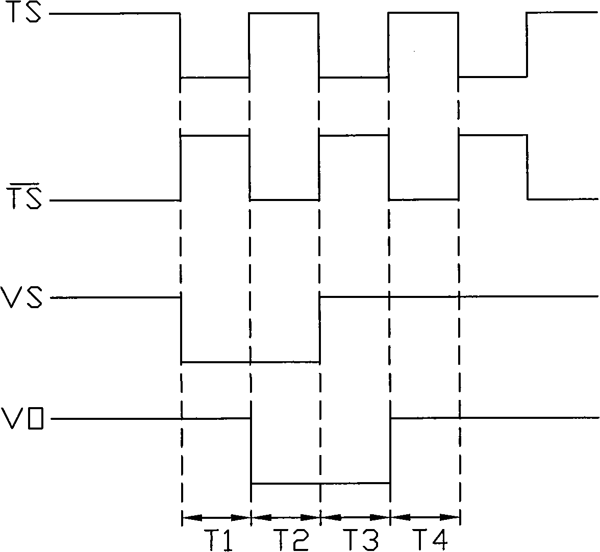
[0026] see image 3, which is a schematic diagram of the first embodiment of the shift register of the present invention. The shift register 2 includes a plurality of shift register units S1 to S(n+1) with the same circuit structure, and the plurality of shift register units S1 to S(n+1) are electrically connected in sequence. Each shift register unit Si (1≤i≤n+1) includes a clock signal input terminal CLOCK, a first input terminal VIN, a second input terminal VINB, a first output terminal VOUT, a second output terminal VOUTB, a high level input terminal VGH and a low level input terminal VGL.

[0027] The first input terminal VIN of the shift register unit S1 is connected to an external circuit, its second input terminal VINB is connected to the second output terminal VOUTB of the shift register unit S2, and its first output terminal VOUT is connected to the shift register unit S2 The first input end of the VOUTB is floating. The first input terminal VIN is used to receive...


PUM


Abstract

The invention relates to a shift register, comprising a plurality of shift register cells which are electrically connected in sequence; and each shift register cell comprises an input circuit and an output circuit. The input circuit is used for providing a reference power level for the output circuit under the control of the former and the next shift register cells. The output circuit is used to provide a pulse for an external circuit under the control of external clock signal or counter-clock signal and the reference power level and to provide a startup pulse for the next shift register cell and a stop pulse for the former shift register cell.

Description

technical field [0001] The invention relates to a shift register and a liquid crystal display device using the shift register. Background technique [0002] At present, a thin film transistor (Thin Film Transistor, TFT) liquid crystal display device has gradually become a standard output device of various digital products. [0003] Generally, a driving circuit of a liquid crystal display device includes a data driving circuit and a scanning driving circuit. The data driving circuit is used to control the display brightness of each pixel unit, and the scanning driving circuit is used to control the turn-on and cut-off of the thin film transistor. Both drive circuits use a shift register as a core circuit unit. Usually, the shift register is composed of a plurality of shift register units connected in series, and the output signal of the previous shift register unit is the input signal of the latter shift register unit. [0004] see figure 1 , is a schematic circuit struct...

Claims


Application Information

Patent Timeline
Patent Type & Authority Applications(China)
IPC IPC(8): G11C19/00G09G3/36
CPCG11C19/28G11C19/00
Inventor 江建学陈思孝
Owner INNOCOM TECH (SHENZHEN) CO LTD
Learn More