
Shift register circuit and pull-up unit thereof

A shift register, circuit technology, applied in static memory, digital memory information, instruments, etc., can solve problems such as power loss

Inactive Publication Date: 2009-01-28
CHI MEI EL +1
View PDF0 Cites 5 Cited by
  • Summary
  • Abstract
  • Description
  • Claims
  • Application Information

AI Technical Summary

Problems solved by technology

[0007] Therefore, one aspect of the present invention is to provide a shift register circuit, so as to avoid the generation of a current path in any operation cycle, to solve the problem of power loss caused by the current path, and to achieve the purpose of power saving

Method used


Image

  • Shift register circuit and pull-up unit thereof
  • Shift register circuit and pull-up unit thereof
  • Shift register circuit and pull-up unit thereof

Examples


Embodiment Construction

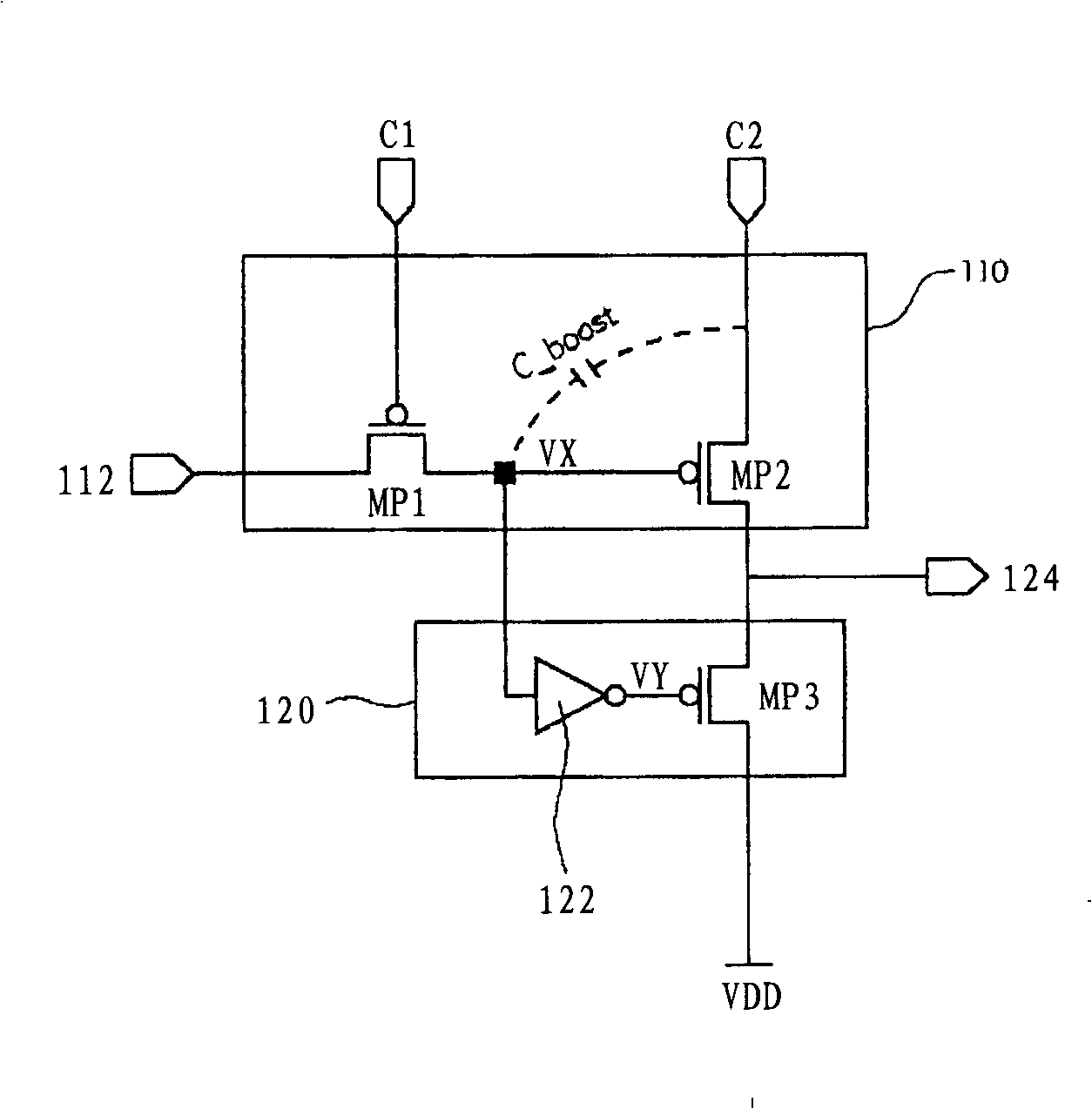
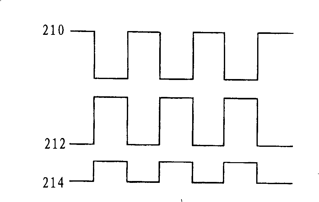
[0053] The feature of the shift register circuit of the present invention is: when operating under any input condition, the shift register circuit of the present invention will not generate current through the inverse relationship between the first clock signal and the second clock signal The path to solve the power consumption problem of the existing current.

[0054] Please refer to Figure 4 , which shows a schematic block diagram of a shift register circuit in a preferred embodiment of the present invention. This shift register circuit is sequentially connected with a plurality of shift registers 240a, 240b, 240c, wherein each shift register (240a, 240b or 240c) is coupled to a first clock terminal (C1a, C1b or C1c) and a second clock terminal. Two clock terminals (C2a, C2b or C2c), and respectively output an output signal to the output terminal (242a, 242b or 242c), wherein, the shift register 240a is coupled to the input terminal 248, and the input of the shift register...


PUM


Abstract

The invention relates to a shift register circuit and an upper pulling unit thereof. The shift register circuit is provided with a plurality of shift registers in serial connection and in sequence; each shift register at least comprises a phase shifting unit and the upper pulling unit, wherein the phase shifting unit receives a first input signal, a first clock signal and a second clock signal; an electrical level of the first clock signal and an electrical level of the second clock signal are reversed phases; and the upper pulling unit is used for pulling an output signal on the output end to the high electrical level. The upper pulling unit at least comprises a logic unit, wherein when the shift register is operated in any period, the upper pulling unit produces no current path.

Description

technical field [0001] The invention relates to a shift register circuit, and in particular to a shift register used for a thin film transistor plane display device. Background technique [0002] Thin Film Transistor Plane Displays have been widely used in portable TVs, mobile phones, In consumer electronics or computer products such as video recorders, notebook computers, desktop monitors, and projection TVs, displays have become the mainstream. [0003] The driving system of the thin film transistor flat panel display includes a source driver (Source Driver) and a scan driver (Scan Driver), etc., and the source driver and the scan driver include a shift register circuit, wherein the shift register circuit is composed of multiple shift registers. The registers are electrically connected in series. Please refer to figure 1 , which shows a schematic diagram of an existing P-Channel Metal Oxide Semiconductor (P-Channel Metal Oxide Semiconductor; PMOS) shift register. The e...

Claims


Application Information

Patent Timeline
IPC IPC(8): G11C19/00G11C19/28G09G3/34
Inventor 曾名骏郭鸿儒黄建翔
Owner CHI MEI EL
Learn More