
Mixed flow fan

A mixed-flow fan and air duct technology, which is applied in the direction of ventilation systems, mechanical equipment, machines/engines, etc., can solve the problems of reduced fan life, corona hazards, overheating, etc., and achieve the effect of reducing vibration and meeting performance requirements

Active Publication Date: 2009-01-21
CHINA RAILWAYS CORPORATION +1
View PDF0 Cites 7 Cited by
  • Summary
  • Abstract
  • Description
  • Claims
  • Application Information

AI Technical Summary

Problems solved by technology

Forcibly using this kind of fan in the power supply of the above-mentioned locomotive will cause corona hazards and reduce the life of the fan, and the motor may overheat if it works for a long time in such a state

Method used


Image

  • Mixed flow fan
  • Mixed flow fan
  • Mixed flow fan

Examples


Embodiment Construction

[0035] The first embodiment of the present invention provides a mixed flow fan suitable for heat dissipation of locomotive inverters. It should be clear that the mixed flow fan can also be used in other similar occasions.

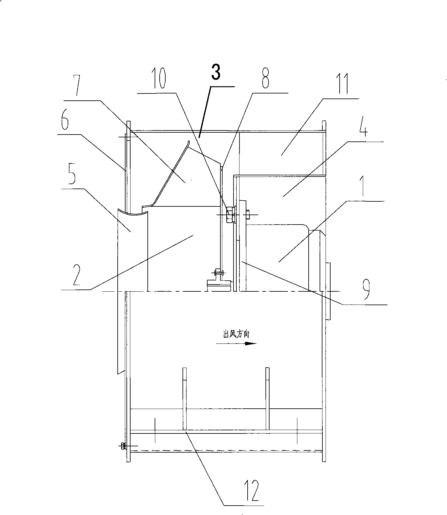
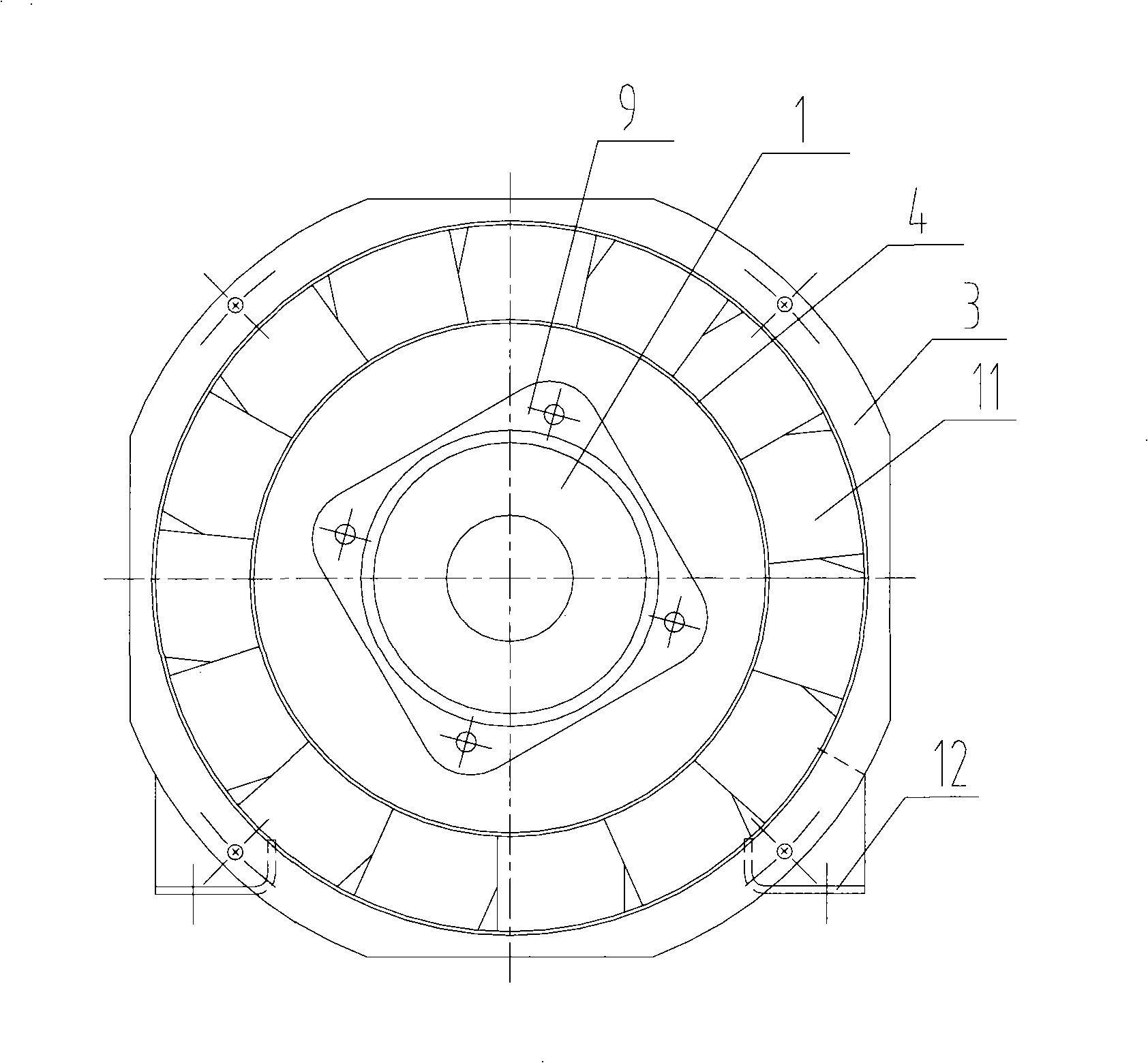
[0036] Please see figure 1 , which is a half-sectional view of the left side of the mixed-flow fan provided by the first embodiment of the present invention. and see also figure 2 , the figure is the front view of the mixed flow fan. The front view direction of the above-mentioned views refers to the direction of viewing the fan from the fan outlet side along the fan axis.

[0037] It can be seen from the figure that the mixed-flow fan includes a drive motor 1 , an impeller 2 , an air cylinder 3 , a guide vane cylinder 4 and guide vanes 11 .

[0038]Wherein, both the air cylinder 3 and the guide vane cylinder 4 are cylindrical, and the diameter and length of the air cylinder 3 are larger than the guide vane cylinder 4 . A plurality of arc-shaped guide...


PUM


Abstract

The invention provides a mixed flow fan, which comprises a driving motor, an impeller wheel, a wind-sock, a guide vane cylinder and a guide vane, one side of a wind inlet of the wind-sock is equipped with a cover plate, the cover plate covers a part area of the circumference of one side of the wind inlet of the wind-sock to reduce the actual wind entering area of the wind inlet, and the diameter of the impeller wheel still keeps adapted to the original wind inlet. The wind inlet of the wind-sock of the fan is equipped with the cover plate, which reduces the actual wind entering area of the fan, can largely increase wind pressure, and enables radiating wind to have a better radiating effect. The optimized implementation mode of the invention further takes measures to improve the quality of radiating wind flow, enables the fan to reduce vibration, and takes vibration insulation measures. The mixed flow fan is particularly suitable for being used in radiating occasions of locomotive inverters, or can be applied to other similar occasions.

Description

technical field [0001] The invention relates to a ventilator, in particular to a mixed flow fan. Background technique [0002] Many production and living occasions need to enhance heat dissipation to avoid heat accumulation. For example, many electrical and electronic components need to dissipate heat during use to avoid component damage due to heat accumulation. [0003] At present, the main heat dissipation method is to use fans to dissipate heat. The fan can provide cooling air with a certain wind pressure and air volume to realize heat dissipation. It is the main means of heat dissipation in many occasions, especially electrical and electronic components. The wind pressure and air volume of the cooling air are positively correlated with the heat dissipation effect. Therefore, to obtain a good heat dissipation effect, the cooling air pressure and air volume provided by the fan must meet the requirements. [0004] In the prior art, cooling fans can be divided into centr...

Claims


Application Information

Patent Timeline
IPC IPC(8): F04D25/14F04D29/40F04D29/26F24F7/00
Inventor 马伯乐荣智林陈燕平杨进峰丁杰忻力
Owner CHINA RAILWAYS CORPORATION
Learn More