
Filling device of filling machine

A filling device and filling machine technology, which is applied in the field of filling devices of filling machines, can solve problems such as product quality affecting sealing yield, inaccurate quantification, and incomplete cleaning, so as to improve matching accuracy and eliminate waste of raw materials , long service life effect

Inactive Publication Date: 2009-01-21
宁波市永宏机械有限公司
View PDF0 Cites 8 Cited by
  • Summary
  • Abstract
  • Description
  • Claims
  • Application Information

AI Technical Summary

Problems solved by technology

[0002] At present, the filling device of the filling machine realizes the connection and closure of the feed port and the discharge port through a three-way cock or a flat rotary valve. The principle is to extend the discharge port into the bottle, and when the liquid rises to When the discharge port is blocked, the quantitative control of the discharge is realized. However, with the quantitative control of this structure, when there is an error in the size of the bottle, the actual capacity in the bottle at this time will change, resulting in Quantification is inaccurate, and with this type of filling device, there is a medium dripping at the discharge port after the filling is completed, especially the granular medium, which seriously affects the product quality and the sealing yield. This filling device also uses a sealing ring, resulting in incomplete cleaning and easy wear

Method used


Image

  • Filling device of filling machine
  • Filling device of filling machine
  • Filling device of filling machine

Examples


Embodiment Construction

[0025] The present invention will be described in further detail below in conjunction with the accompanying drawings and specific embodiments:

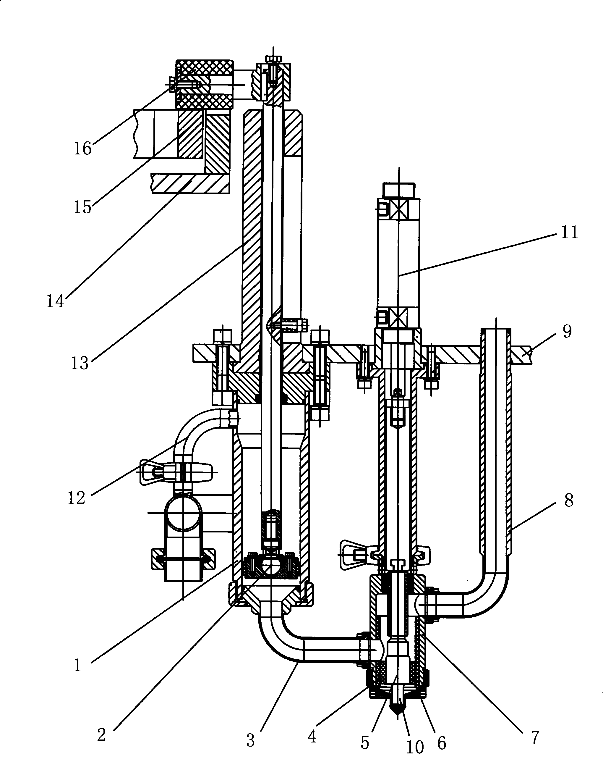
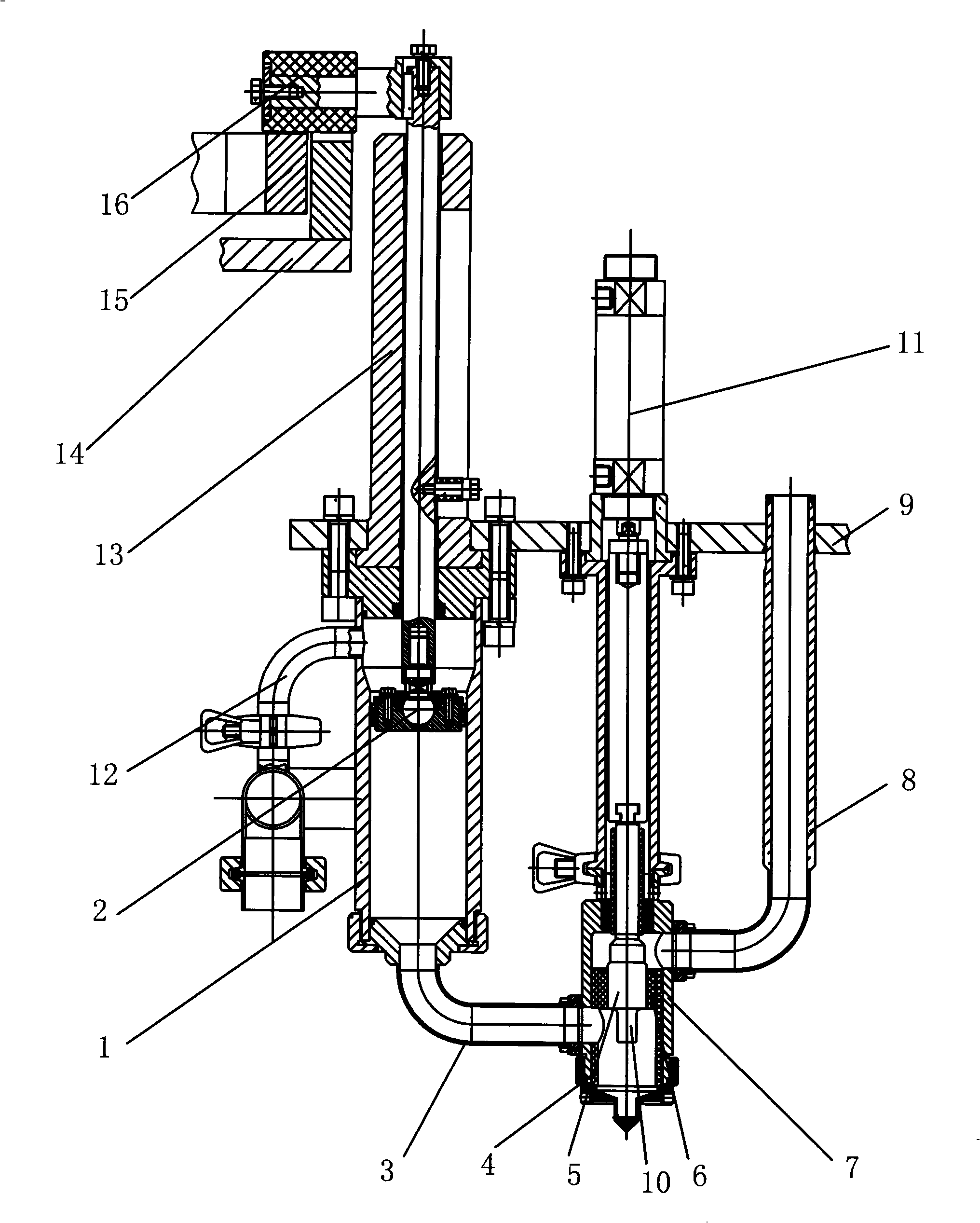
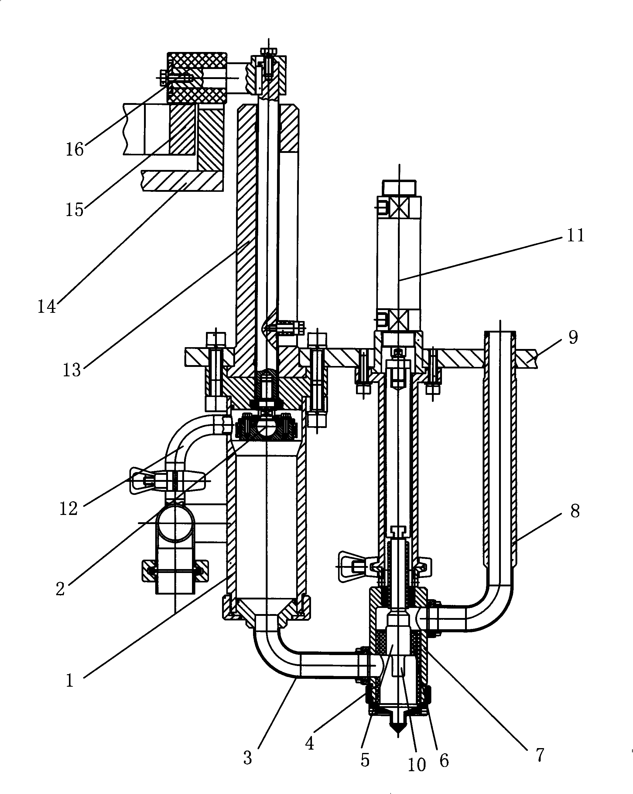
[0026] see Figure 1 to Figure 4 , The filling device of the filling machine is mainly composed of a quantitative cylinder 1, a connecting pipe, an on-off valve 7, and a valve core 5.

[0027] An inner piston 2 is arranged inside the quantitative cylinder 1 , and a first power mechanism is arranged above the inner piston 2 , and the power mechanism can make the inner piston 2 move up and down along the quantitative cylinder 1 . The bottom of the quantitative cylinder 1 is provided with a first connecting pipe 3, the quantitative cylinder 1 communicates with the first connecting pipe 3 inside, and the liquid flows from the first connecting pipe 3 to the quantitative cylinder 1 or through the first connecting pipe 3. Flow out of the quantitative cylinder 1.

[0028] The other end of the first connecting pipe 3 is connected with an on-...


PUM


Abstract

The invention discloses a filling device for a filling machine, having a structure that the filling device comprises a quantity cylinder body, connecting pipes, a switch valve and a valve core. The structure has the main points that an inner piston is arranged inside the quantity determining cylinder body; a first power mechanism is arranged above the inner piston; a first connecting pipe is arranged below the quantity determining cylinder body; the quantity determining cylinder body is communicated with the inside of the first connecting pipe; the other end of the connecting pipe is connected with the switch valve, and is communicated with a hole arranged on one side of the switch valve; the valve core is arranged inside the switch valve; the upper end of the valve core is provided with a second power mechanism; the other side of the switch valve is connected with a second connecting pipe; the other end of the second connecting pipe is connected with a material cylinder of the filling machine; and a filling valve adopts the rising height of the inner piston to realize the quantity. As the size of the filling valve is fixed, the rising height of the filling valve is the same, the capacity is not changed, and the quantity is accurate.

Description

technical field [0001] The invention relates to a filling machine, in particular to a filling device of the filling machine Background technique [0002] At present, the filling device of the filling machine realizes the connection and closure of the feed port and the discharge port through a three-way cock or a flat rotary valve. The principle is to extend the discharge port into the bottle, and when the liquid rises to When the discharge port is blocked, the quantitative control of the discharge is realized. However, when the quantitative control of this structure is adopted, when there is an error in the size of the bottle, the actual volume in the bottle will change at this time, resulting in The quantification is inaccurate, and this type of filling device has media dripping at the discharge port after filling, especially with granular media, if it is meat, it will seriously affect the product quality and the sealing yield. In addition, This filling device also uses a ...

Claims


Application Information

Patent Timeline
Patent Type & Authority Applications(China)
IPC IPC(8): B67C3/26B67C3/28
Inventor 李岱崇李代夫
Owner 宁波市永宏机械有限公司
Learn More