
Detection jig

A technology for detecting fixtures and through-holes, which is applied in the direction of measuring devices, optical instrument testing, and machine/structural component testing, etc. It can solve problems such as affecting product qualification rate, reducing the accuracy of camera brackets, and large fixture movement. , to avoid the movement of the detection point, reduce the possibility of relative displacement, and improve the accuracy

Pending Publication Date: 2022-04-01
SUZHOU BOZHON ROBOT CO LTD
View PDF0 Cites 0 Cited by
  • Summary
  • Abstract
  • Description
  • Claims
  • Application Information

AI Technical Summary

Problems solved by technology

At present, there is a light hole on the camera bracket, and the size of the light hole needs to be detected, that is, the front and back of the fixed camera bracket need to be exposed. Therefore, a detection hole is opened on the jig to ensure that the front and back of the camera bracket are Both can be exposed, and the camera bracket is fixed on the jig only by the claws on the left and right sides of the camera bracket, and in order to avoid leaving clamp marks on the camera bracket, the clamping force on the camera bracket is relatively small. The friction between the camera bracket and the jaws is small, and the camera bracket is more likely to move relative to the fixture during the movement process, causing the detection point on the camera bracket to move, reducing the accuracy of camera bracket detection and affecting the product. pass rate

Method used


Image

  • Detection jig
  • Detection jig
  • Detection jig

Examples


Embodiment Construction

[0033] In order to make the technical problems solved by the present invention, the technical solutions adopted and the technical effects achieved clearer, the technical solutions of the embodiments of the present invention will be further described in detail below in conjunction with the accompanying drawings. Obviously, the described embodiments are only the technical solutions of the present invention. Some, but not all, embodiments. Based on the embodiments of the present invention, all other embodiments obtained by those skilled in the art without making creative efforts belong to the protection scope of the present invention.

[0034] In the description of the present invention, unless otherwise clearly specified and limited, the terms "connected", "connected" and "fixed" should be understood in a broad sense, for example, it can be a fixed connection, a detachable connection, or an integrated ; It can be a mechanical connection or an electrical connection; it can be a d...


PUM


Abstract

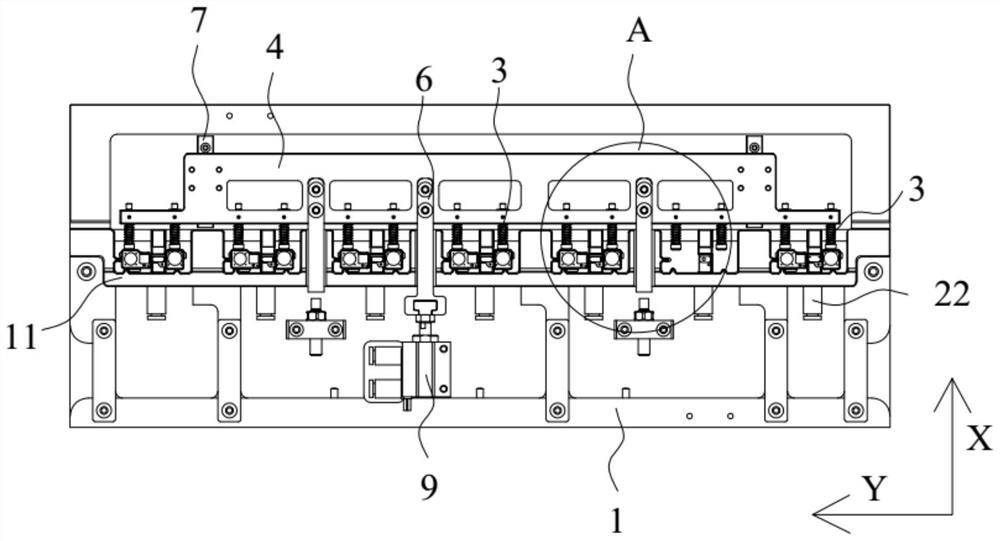
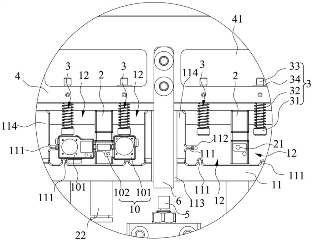
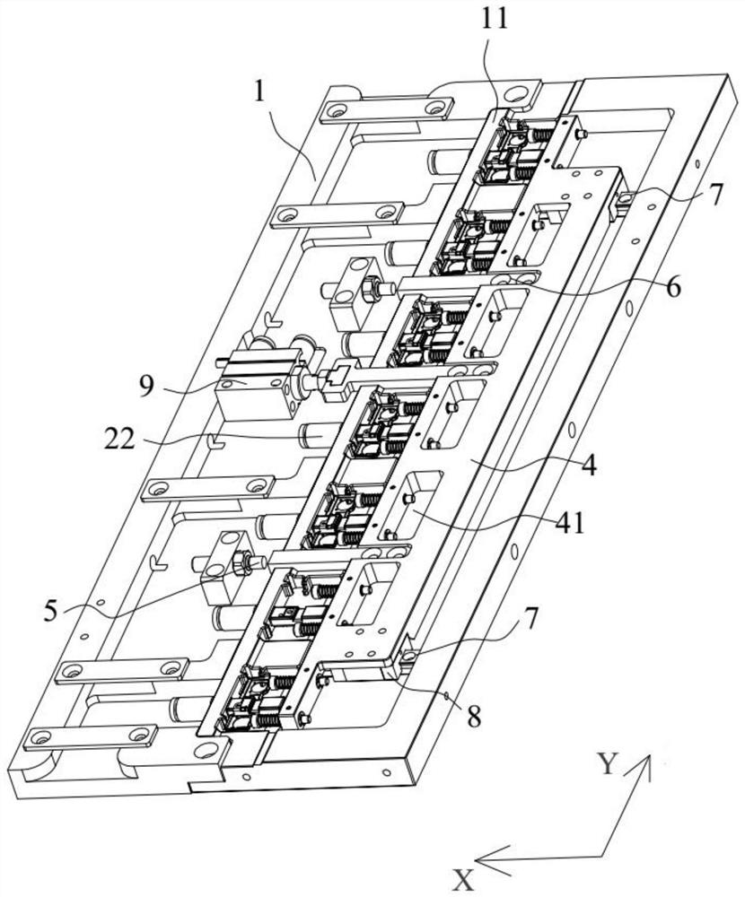
The invention relates to the technical field of detection jigs, and discloses a detection jig. The detection jig comprises a carrying table, a bearing beam and a clamping unit. A detection through hole is formed in the carrying table, a fixing part is arranged on the carrying table in a protruding mode, and the fixing part is located on one side of the detection through hole in the first direction; the bearing beam is arranged at the detection through hole and can bear a part, and one end of the bearing beam is connected to the fixing part and extends in the first direction so as to divide the detection through hole into two detection channels; the clamping unit is arranged on the carrying table and located on the other side of the detection through hole in the first direction, and the clamping unit can be close to or away from the fixing part in the first direction so as to clamp or loosen the part. According to the detection jig provided by the invention, the part can be stably fixed on the detection jig, the possibility of relative displacement between the part and the detection jig is reduced, and the accuracy of part detection is improved.

Description

technical field [0001] The invention relates to the technical field of detection jigs, in particular to a detection jig. Background technique [0002] The camera bracket needs to undergo various quality inspections before leaving the factory. Generally, before the camera bracket is tested, the camera bracket is fixed on the testing fixture to prevent the camera bracket from moving during the testing process. After the camera bracket has passed one of the inspections, it is necessary to use equipment such as manipulators to grab the inspection jig, and move the jig and camera bracket to the subsequent inspection station as a whole. At present, there is a light hole on the camera bracket, and the size of the light hole needs to be detected, that is, the front and back of the fixed camera bracket need to be exposed. Therefore, a detection hole is opened on the jig to ensure that the front and back of the camera bracket are Both can be exposed, and the camera bracket is fixed ...

Claims


Application Information

Patent Timeline
Patent Type & Authority Applications(China)
IPC IPC(8): G01M11/00
Inventor 王义勇赵娅娟韦武光林道漆阮水安
Owner SUZHOU BOZHON ROBOT CO LTD
Learn More