
Control method of rolling mill capable of preventing slipping

A control method and anti-slip technology, which is applied in the field of cold rolling in the metallurgical field, can solve problems such as rack tension fluctuations and broken belts, and achieve the effects of ensuring rolling stability, improving accuracy, and avoiding slipping

Active Publication Date: 2008-12-31
宝钢日铁汽车板有限公司
View PDF0 Cites 25 Cited by
  • Summary
  • Abstract
  • Description
  • Claims
  • Application Information

AI Technical Summary

Problems solved by technology

[0009] The object of the present invention is to provide a control method for rolling mill anti-slip, which can solve the deficiencies of the prior art, eliminate or alleviate the problem of rolling mill slippage during high-speed rolling, improve the working efficiency of the stand, and at the same time avoid Frequent adjustments caused by deceleration lead to tension fluctuations or even broken belts between racks

Method used


Image

  • Control method of rolling mill capable of preventing slipping
  • Control method of rolling mill capable of preventing slipping
  • Control method of rolling mill capable of preventing slipping

Examples


Embodiment 1

[0045] Production status: The production specification of the rolling mill is 3.5mm / 0.8mm×1413mm, when the tension setting value before the 3 stands is T SET(3) It is 38KN, and the setting value of rear tension is T SET(2) 42KN, rolling speed V 3 When it is 895mpm, the mill stand 3 slips, and the forward slip value f 3 It is -1.23%. Due to the slippage of the 3rd stand, the strip steel in the rolling mill stand shakes, and the thickness of the stand fluctuates greatly, which affects the stable production of the rolling mill.

[0046] Adjustment status: put into the rolling mill anti-skid control function and debug. First adjust the front tension adjustment amount T of the 3 racks slip(3) , the key here is to determine the increment ξ and the rate of change of ξ each time. The process of determining ξ is: (0.8KN→0.7KN→0.6KN→0.5KN), and the process of determining the step change rate of ξ is: (0.8KN / 20ms→0.4KN / 20ms→0.2KN / 20ms→0.1KN / 20ms). In order to improve the responsivenes...

Embodiment 2

[0047] Embodiment 2: (When the 3-frame slips, the slippage is eliminated by adjusting the front tension and the rear tension of the 3-frame)

[0048] Production status: The production specification of the rolling mill is 3.0mm / 0.5mm×1200mm, when the tension setting value before the 3 stands is T SET(3) It is 29KN, and the setting value of rear tension is T SET(2) 34KN, rolling speed V 3 When it is 901mpm, the rolling mill 3 stand slips, at this time the forward slip value f 3 It is -1.3%. Due to the slippage of the 3rd stand, the strip steel in the rolling mill stand shakes, and the thickness of the stand fluctuates greatly, so the rolling mill cannot produce stably.

[0049] Adjustment status: put into the rolling mill anti-skid control function and debug. First, adjust with 3 racks each setting increment ξ0.5KN and ξ rate of change 0.1KN / 20ms until the pre-tension setting value T SET(3) When it is greater than 31.9KN (greater than X times the set value), the forward slid...


PUM


Abstract

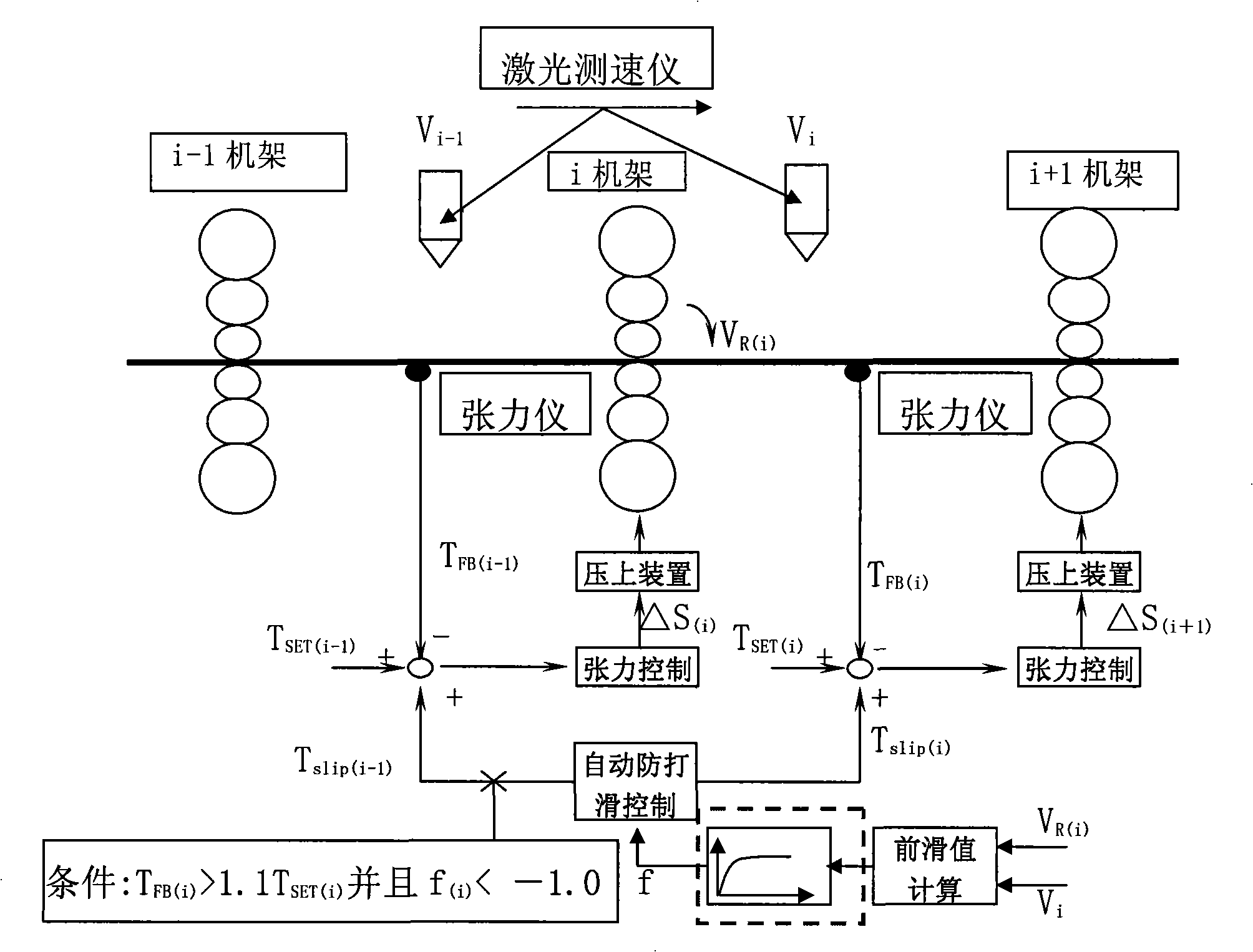
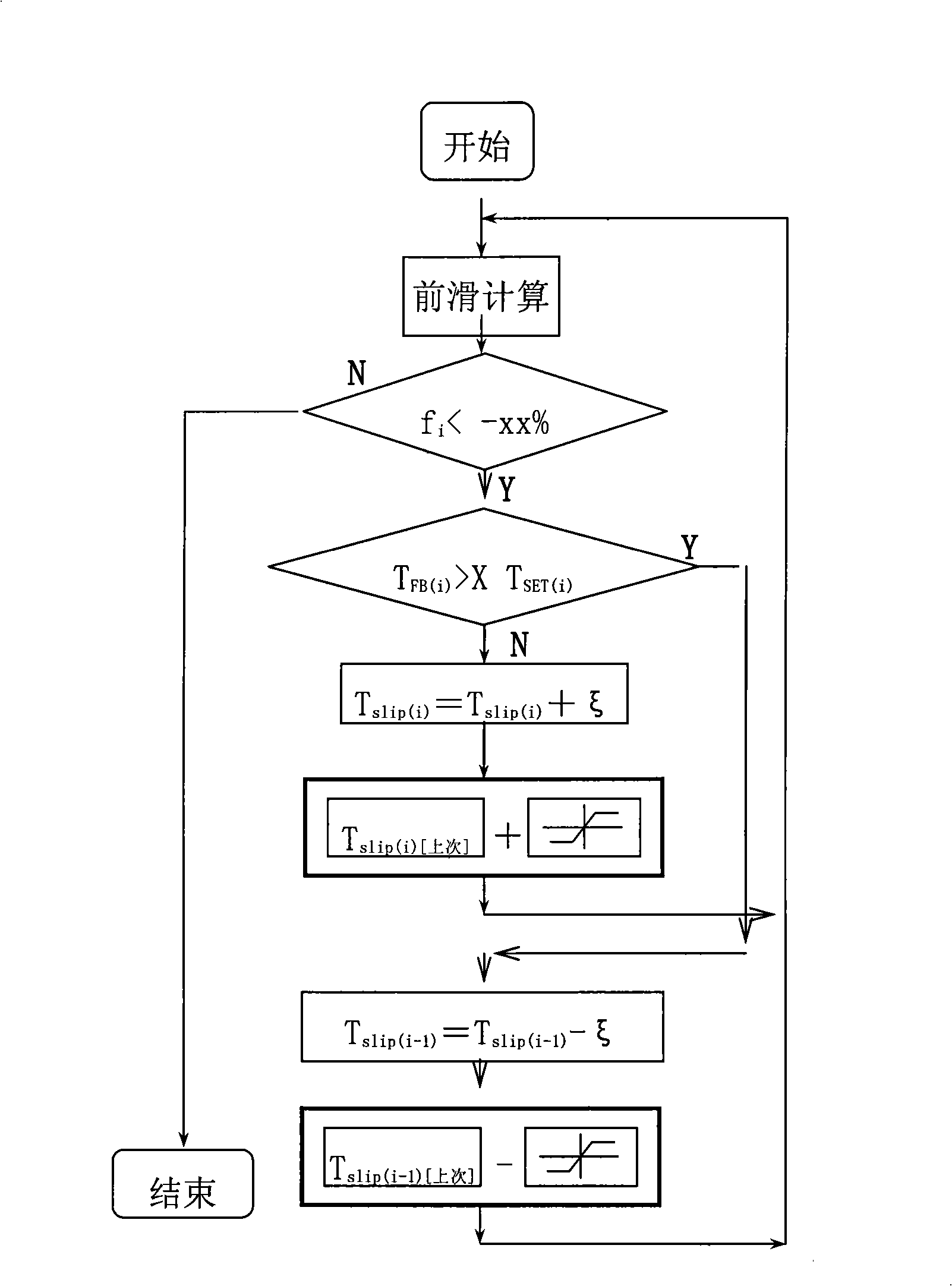
The invention discloses a control method for preventing a rolling mill from slipping, which comprises the following steps: A, the speeds of a strip steel and a roller are measured by a velometer, a forward slip value of a frame is calculated, and step B is followed; B, the forward slip value is judged, when the forward slip value is less than a certain determined value, step C is carried out, otherwise, the control is stopped; C, the forward pull of the frame is increased, measured and judged, when the forward pull is more than a certain determined value, step D is carried out, otherwise, step A is carried out; D, a backward pull of the frame is decreased, and step A is carried out. The method can solve the problem that the rolling mill slips in the course of high-speed rolling, can improve work efficiency of the frame, and can avoid pull fluctuation of the frame even or strip breakage caused by the frequent adjustment when the frame is accelerated or decelerated.

Description

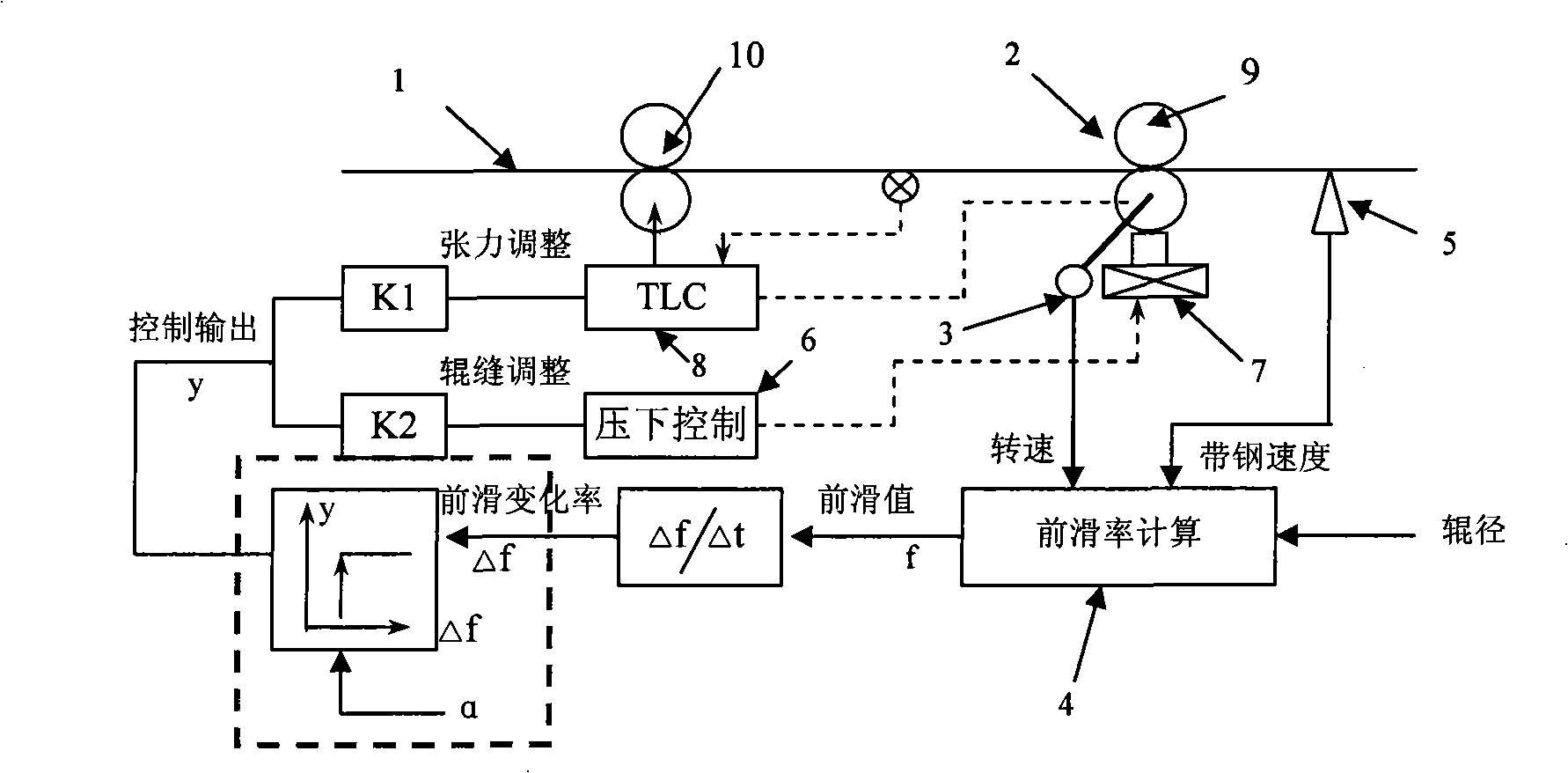
technical field [0001] The invention relates to cold rolling technology in the field of metallurgy, in particular to an anti-slip control method for acid rolling mills. Background technique [0002] The acid rolling unit is the front unit in the cold rolling process. During the high-speed rolling process, problems such as slipping and scratches sometimes occur, which affect the stability of rolling, and its product quality defects will also affect or be transmitted to the subsequent unit. , resulting in product surface quality defects. Existing anti-skid control methods such as figure 1 As shown, among them, 1 is the strip steel, 2 is the work roll, 3 is the roller speed detector, 4 is the front slip rate calculation module, 5 is the strip speed detector, 6 is the lower control device, and 7 is the main pressure upper oil cylinder , 8 is the tension control device. This technology monitors the forward slip value of the rack in real time through the forward slip rate calcu...

Claims


Application Information

Patent Timeline
Patent Type & Authority Applications(China)
IPC IPC(8): B21B37/48B21B38/00
Inventor 张伟肖至勇
Owner 宝钢日铁汽车板有限公司
Learn More