
LCD device and backlight device

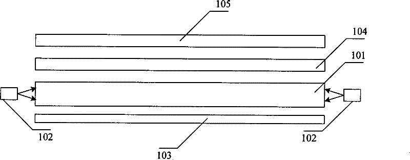
A technology of backlight device and liquid crystal display, applied in the field of backlight

Active Publication Date: 2012-05-30
BOE TECH GRP CO LTD
View PDF0 Cites 1 Cited by
  • Summary
  • Abstract
  • Description
  • Claims
  • Application Information

AI Technical Summary

Problems solved by technology

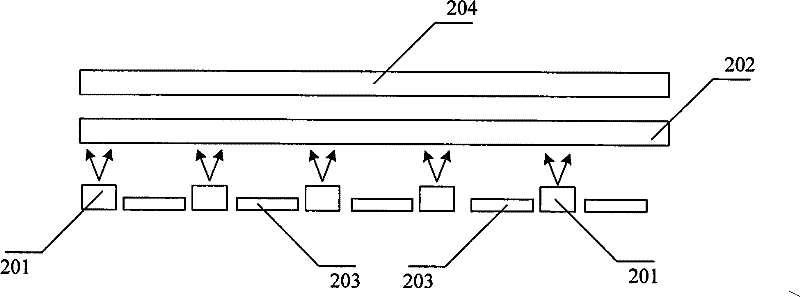
In the LED backlight structure, a certain light mixing distance must be obtained between LED201 and the diffuser, so that the LED backlight is not suitable for thin
If the light mixing distance is reduced by reducing the wick spacing, thereby reducing the thickness of the backlight source, since reducing the wick spacing requires reducing the brightness of each LED, it is necessary to increase the number of LEDs used, which increases the production cost of the LED backlight

Method used


Image

  • LCD device and backlight device
  • LCD device and backlight device
  • LCD device and backlight device

Examples


Embodiment Construction

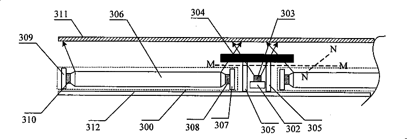
[0029] Such as image 3 Shown is a side view of an embodiment of the backlight device of the present invention, Figure 4 for image 3 A top view of the backlight device of the illustrated embodiment on the M-N plane. See also image 3 and Figure 4 , the backlight device of the embodiment of the present invention includes a casing 301, and the casing 301 may be a plastic product. Housing 301 is provided with more than one light emitting unit 300 distributed on the same plane (such as image 3 As shown in the dotted line box), a first PCB302 is arranged between two adjacent light-emitting units 300, and more than one first light-emitting source 303 is arranged on the first PCB302, and the first light-emitting source 303 is surface-attached on the first PCB302 . As a specific embodiment, the first light emitting source 303 may be a CCFL or a white LED, or a white LED including chips of three primary colors of red, green and blue. Since the red, green, and blue primary co...


PUM


Abstract

The invention discloses an LCD apparatus and a backlight device. The backlight device comprises a shell body; optical diaphragms and transmission sheets are arranged in the shell body; more than one light emitting unit is arranged between the optical diaphragms and the transmission sheets in the shell body; first printed circuit boards are arranged between the adjacent light emitting units; more than one first light emitting source is arranged on the first printed circuit boards; diffuser sheets covering the areas between the light emitting units are arranged above the first light emitting sources and are fixed on the shell body through a transparent support column; each light emitting unit comprises a light guide plate; a second printed circuit board is arranged on a first side of the light guide plate below the diffuser sheets; more than one second light emitting source is arranged between the second printed board and the light guide board; a third printed circuit board is arranged on the second side of the light guide board corresponding to the first side; and more than one third light emitting source is arranged between the third printed circuit board and the light guide board. The backlight device disclosed by the invention is applicable to large size LCD apparatuses and is thin.

Description

technical field [0001] The invention relates to backlight technology, in particular to a liquid crystal display device and a backlight device. Background technique [0002] Since the liquid crystal itself does not emit light, in various liquid crystal display devices such as liquid crystal displays and liquid crystal TVs, it is necessary to rely on external light sources to achieve display. Currently, a liquid crystal display device (Liquid Crystal Display, hereinafter referred to as LCD) has gradually become a mainstream of flat panel displays. LCD is divided into reflective LCD and transmissive LCD. Among them, reflective LCD relies on external ambient light, while transmissive LCD relies on backlight. Therefore, the thickness of the backlight source directly determines the thickness of the liquid crystal display device. To realize an ultra-thin display device, it is necessary to reduce the thickness of the backlight source. [0003] LCD backlight sources are divided in...

Claims


Application Information

Patent Timeline
Patent Type & Authority Patents(China)
IPC IPC(8): G02F1/13357G02B6/00G02B1/04H05K1/18
Inventor 孙小斌万丽芳赵星星王刚张丽蕾
Owner BOE TECH GRP CO LTD
Learn More