
Thin molded article

A thin-thickness, molded product technology, applied in the field of thin-thickness molded products, can solve problems such as insufficient injection pressure, thin-thickness plate thickness deviation, molten resin cannot be rotated to the end of the thin-thickness plate, etc.

Inactive Publication Date: 2008-12-17
DAISAN
View PDF2 Cites 3 Cited by
  • Summary
  • Abstract
  • Description
  • Claims
  • Application Information

AI Technical Summary

Problems solved by technology

[0005] (2) When the sheet is drawn in a vacuum, the thickness is limited to 0.6 mm. If it is 0.4 mm, there will be holes in the corners. However, in injection molding, the structure of the pass type , Thin thickness molding of about 0.4mm is possible
[0008] However, in conventional injection molding, molding with a thickness thinner than 1 mm is not suitable because of the following disadvantages
[0009] (1) Although it is effective to inject the injection pressure of the molten resin at a low pressure, due to insufficient injection pressure, the material cannot reach the end of the thin plate. part missing
[0010] (2) If the injection pressure of the molten resin is increased to a high pressure in order not to cause part of the thin flat plate part to be missing, the defect of the thin flat plate part will be improved. Burrs occur on the outer edge of the flat plate
[0011] (3) In order to inject the molten resin to the end of the thin flat plate part, there is also a method of raising the resin temperature to make the fluidity excellent, but for this, the gas or air generated from the high-temperature molten resin stays in the mold, and the molten resin may Disadvantages of not being able to rotate to the end of thin-thickness slabs
[0012] (4) Especially in the case of thin thickness molding, depending on the accuracy of the model or the performance of the molding machine, there is also the disadvantage of uneven thickness and thickness deviation of the thin thickness plate.
[0017] In the case of the mesh filter (filter) of Patent Document 2, since the male and female forms are closely matched on both sides in a linear shape, there is no possibility of uneven thickness, and since the abutting area is also smaller than that of a flat plate, the induction zone of the filter is only The effect of temporarily accumulating the pressure of the molten resin with fine grooves and releasing it powerfully

Method used


Image

  • Thin molded article
  • Thin molded article
  • Thin molded article

Examples


Embodiment

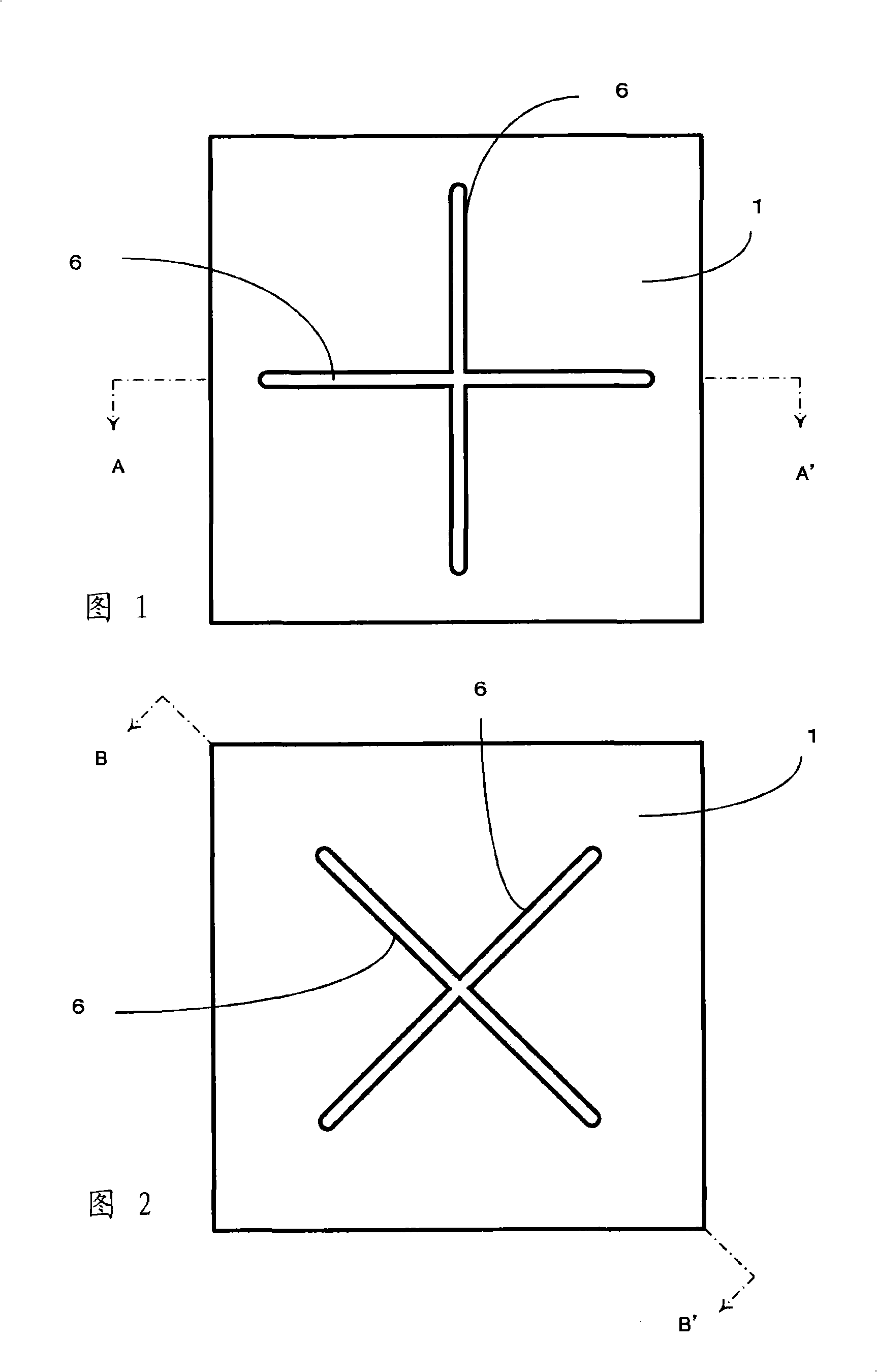
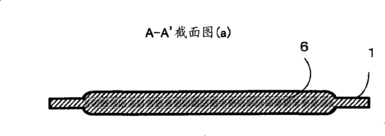
[0085] Fig. 1 shows an example of a plastic molded article having a thin flat plate structure of the present invention, in a manner extending from the central portion of the thin flat plate 1 to the direction of its outer edge, by providing a plurality of induction belts 6, a cross-shaped An induction zone 6 is formed. The induction zone 6 is a thick or wide rib for promoting the flow of the molten resin in the mold. Although not shown in the figure, the molten resin is poured into the mold on the cross-shaped rib or in the center. The gate is set. The molten resin flowing from the gate into the induction zone 6 flows toward the outer edge, and also flows from the periphery of the rib to the thin plate 1 .

[0086] Since the thick-diameter induction band 6 is provided radially from the center of the thin plate toward its outer edge, and the leading end of the induction band 6 does not reach the outer edge of the thin plate 1, the molten resin injected into the mold is After ...


PUM


Abstract

The thin molded article of the present invention includes a thin flat plate 1 and dam / discharge ribs 6 provided on the thin flat plate having a shape in which bar-type ribs having wide or large diameters extend radially from the center of the molded article. The tips of the bar-type ribs having wide or large diameters have a shape that allows the molten resin injected from a gate into a cast to be accumulated temporarily before it flows into said thin plate, thereby providing a configuration in which the tips of said ribs do not reach the outer edge of the molded article.

Description

technical field [0001] The present invention relates to articles that can be used for plastic products of thin thickness (thin meat), and related to molded products such as flat film sheets or various storage containers, especially to provide Molded products in the shape of a thin flat plate or box without bending, skewing or uneven thickness. Background technique [0002] For existing thin plastic molded products, it is common knowledge to effectively use techniques such as vacuum pulling with complicated structures in order to produce thin flat plates or box shapes without bending or skewing. However, even if technologies such as vacuum gravity are used, in plastic molding with an ultra-thin thickness of less than 1mm, due to the thinness, there are disadvantages such as difficulty in using vacuum gravity, poor release of molded products under the action of vacuum gravity, and larger devices. . [0003] Therefore, the present invention is intended to produce thin-thickne...

Claims


Application Information

Patent Timeline
Patent Type & Authority Applications(China)
IPC IPC(8): B29C45/26
Inventor 小泷大藏
Owner DAISAN
Learn More