Spacing phase shifter used for synchronous phase shift interferometer

A technology of synchronous phase shifting and phase shifting, which is applied in the direction of instruments, scientific instruments, and optical devices, etc., and can solve the problems of large position matching errors of phase shifting interference images, large position matching errors, difficulties in optical path debugging and structural assembly, etc. , to achieve precise spatial position matching, high position matching accuracy, and high contrast consistency

Inactive Publication Date: 2010-07-07
SHANGHAI INST OF OPTICS & FINE MECHANICS CHINESE ACAD OF SCI
View PDF0 Cites 0 Cited by
  • Summary
  • Abstract
  • Description
  • Claims
  • Application Information

AI Technical Summary

Problems solved by technology

[0009] 2. Precise synchronous control is required
[0010] 3. It is difficult to accurately control the amount of phase shift
The phase delay error of the wave plate, the azimuth error of the fast axis and its position tilt error, the azimuth error of the polarizer and its low extinction ratio will all introduce phase shift errors, so that the phase shift amount cannot be accurately controlled
[0011] 4. Large position matching error
The measurement sub-beams and reference sub-beams of different optical paths form phase-shifted interference images on different image sensors. The difference in optical paths and the position differences of image sensors will cause the relative positions of multiple interference images to be different. The rotation amount of optical components and image sensors The difference in the difference and the difference in the amount of inclination will cause different deformations in different interference images, so that the position matching error between the phase-shifting interference images will be large
[0012] 5. Complex structure and difficult assembly and adjustment
The spatial phase shifter splits light twice to form multiple sub-beam groups to obtain three or four phase-shifted interference images. The multiple sub-beam groups are completely separated and non-parallel in space, making the optical and mechanical structures complex and large in size. At the same time, the optical path The debugging and assembly of the structure are also difficult

Method used


Image

  • Spacing phase shifter used for synchronous phase shift interferometer
  • Spacing phase shifter used for synchronous phase shift interferometer
  • Spacing phase shifter used for synchronous phase shift interferometer

Examples


Embodiment Construction

[0030] The present invention will be further described below in conjunction with the accompanying drawings and embodiments, but the protection scope of the present invention should not be limited thereby.

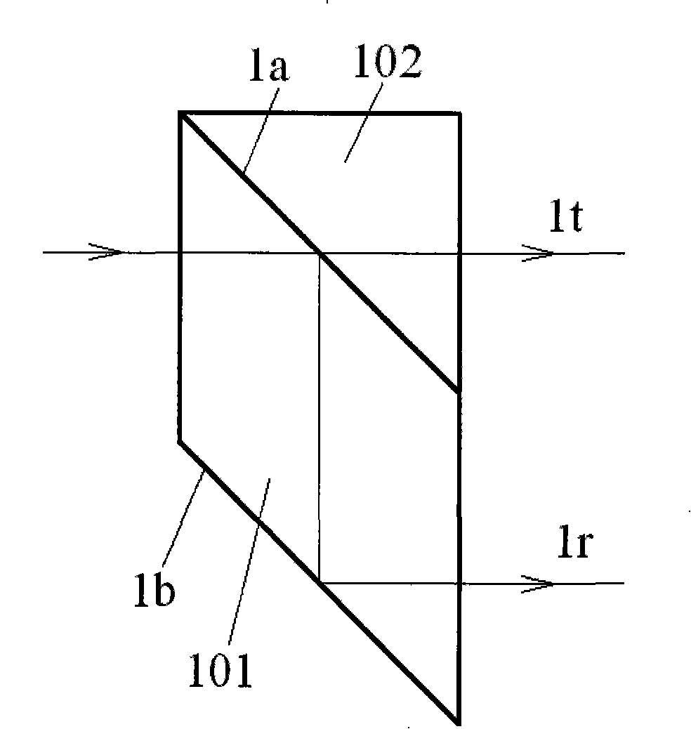
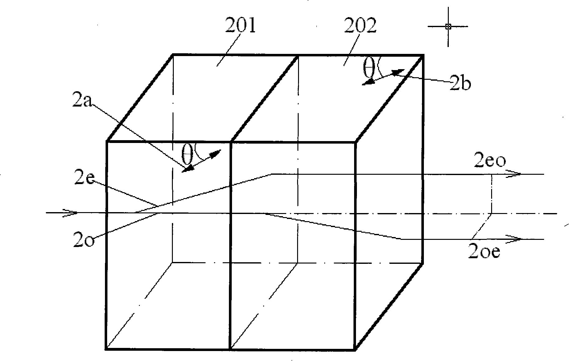
[0031] see first figure 1 , figure 1is the optical path diagram of the space phase shifter of the present invention. As can be seen from the figure, the spatial phase shifter of the present invention is composed of a parallel beam-splitting prism 1, a Savatt polarizer 2 and an image sensor 3, and the parallel beam-splitting prism 1, Savatt polarizer 2 and the image sensor 3 are in the progress of the light beam in sequence direction. The incident plane of the parallel beam splitting prism 1 coincides with its beam splitting plane. The main section of the crystal plate in Savatt polarizer 2 forms an angle of 45° with the beam splitting plane of parallel beam splitting prism 1, and the beam splitting plane of Savat polarizer 2 and the beam splitting plane of parallel beam ...


PUM


Abstract

A space phase shifter used in a synchronous phase-shifting interferometer is characterized by only consisting of a parallel beam splitter prism, a Savart polarizer and an image sensor. The parallel beam splitter prism, the Savart polarizer and the image sensor are arranged on the running direction of the beam in turn. The space phase shifter of the invention has the characteristics of high consistency of contrast, without synchronous control, premise phase-shifting amount, high precision of position matching, simple and compact structure as well as easy assembling and adjusting.

Description

technical field [0001] The invention relates to the field of optical interferometry, and relates to a spatial phase shifter for a synchronous phase-shifting interferometer, in particular to a spatial phase shifter for simultaneously receiving multiple phase-shifting interference images with a single image sensor. Background technique [0002] The phase-shifting interferometer uses phase-shifting technology to assist in the extraction of phase information, which can obtain high measurement accuracy and achieve equal-precision measurement over the entire measurement area. Common phase-shifting interferometers use piezoelectric ceramics to drive the standard mirror to move or change the laser wavelength to achieve phase shifting. Multiple phase-shifting interference images are collected at different times, which is called a time-domain phase-shifting interferometer. The time-domain phase-shifting interferometer has very strict requirements on the use environment due to the chan...

Claims


Application Information

Patent Timeline
Patent Type & Authority Patents(China)
IPC IPC(8): G01B9/02G01J9/02G02B5/04G02B5/30
Inventor 曾爱军郭小娴江晓军黄惠杰王向朝
Owner SHANGHAI INST OF OPTICS & FINE MECHANICS CHINESE ACAD OF SCI
Why Eureka
Try Eureka